Tetrafluoroethylene/hexafluoropropylene copolymer and the production method thereof, and electrical wire

a technology of hexafluoroethylene and production method, which is applied in the direction of plastic/resin/waxes insulators, organic insulators, coatings, etc., can solve the problems of lump size, melt-processable fluororesin composition, and inability to substantially reduce the occurrence frequency of lumps, so as to reduce the defect of high-speed extrusion coating, improve moldability in melt extrusion molding, and reduce the effect of transmittance loss

Active Publication Date: 2010-12-16
DAIKIN AMERICA INC +1
View PDF20 Cites 17 Cited by
  • Summary
  • Abstract
  • Description
  • Claims
  • Application Information

AI Technical Summary

Benefits of technology

[0010]In view of the above, the objective of the invention is to give a tetrafluoroethylene / hexafluoropropylene copolymer with improved moldability in melt extrusion molding, especially with significant reduction of defects in high-speed extrusion coating of an electrical wire and with manufacturability of an electrical wire with smaller transmission loss (attenuation).

Problems solved by technology

These techniques can reduce the size of a lump which is produced between a coating resin and a conductive wire in some degree but they can't reduce the occurrence frequency of the lump substantially.
However, this melt-processable fluororesin composition can't reduce the occurrence frequency of the lump substantially as well as the melt-processable fluororesin in which PTFE powder is mixed with FEP powder.
Moreover, fluctuation of capacitance is larger and the electrical properties of the final products made from the melt-processable fluororesin composition are worse when a smaller lump is produced.
However, it is not clear that this PFA composition can give an electrical wire without any defects in high-speed extrusion coating of an electrical wire.

Method used


Image

  • Tetrafluoroethylene/hexafluoropropylene copolymer and the production method thereof, and electrical wire
  • Tetrafluoroethylene/hexafluoropropylene copolymer and the production method thereof, and electrical wire

Examples


working example 1

Synthesis Example 1

[0050]8163.5 lbs. of deionized water (including 3.5 lbs. of ammonium ω-hydroxyfluorocarbonate) was added into a glass-lined autoclave with an agitator (12,000 L volume). After that, the autoclave was vacuumed and filled with nitrogen gas well. After this, after the autoclave was vacuumed, 8459 lbs. of HFP was added into the autoclave. While the deionized water and HFP were agitated vigorously in the autoclave, the inner temperature was set at 89.6 F and 950 lbs. of TFE and 92 lbs. of PPVE were added into the autoclave. Next, the inner pressure of the autoclave was set at 150.6 psi, and 51.8 lbs. of 8 wt % di(ω-hydroperfluorohexanoyl) peroxide (abbreviated to “DHP” in the following) perfluorohexane solution was added into the autoclave to initiate polymerization. 51.8 lbs. of 8 wt % DHP perfluorohexane solution was added into the autoclave, and 1.7 psig of the inner pressure was reduced 2 hours later and 4 hours later from the initiation of the polymerization. Furt...

working example 2

Synthesis Example 2

[0075]After the pellet obtained in the synthesis example 1 was inserted into a vacuum vibration type reactor of VVD-30 (manufactured by OKAWARA MFG. CO., LTD.), the pellet was heated to 200 degree C. After the reactor was vacuumed, F2 gas diluted by 20 wt % with N2 gas was introduced into the reactor up to the atmospheric pressure. F2 gas was introduced again after the reactor was vacuumed three hours later from the first introduction of F2 gas. The operation of the F2 gas introduction described above and vacuuming was carried out 6 times. After the reaction was completed, F2 gas in the reactor was replaced with N2 gas and deaeration of the pellet was carried out at 180 degree C. for 8 hours. The composition of the pellet after the reaction was TFE 87.9:HFP 11.1: PPVE 1.0 in weight. The melting point was 256.8 degree C. The MFR at 372 degree C. was 23.5 g / 10 minutes. The sum of the number of thermally unstable end group and the number of —CF2H end group per 1×10⁶ ...

production example 1

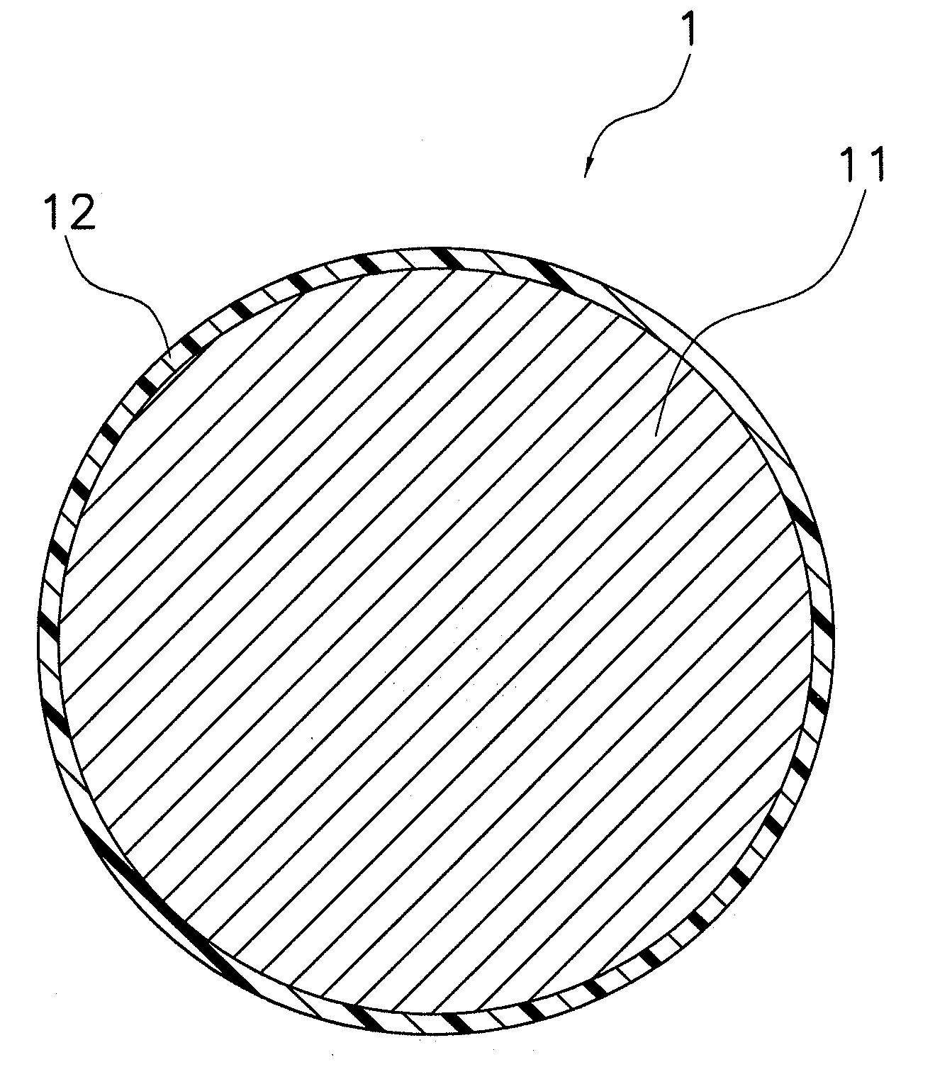
[0077]Wire coating was carried out using the FEP of the synthesis example 2 described above as an insulating coating material (core material). After this, a single braid was formed onto the FEP and then the FEP of the synthesis example 2 as a protective coating (sheath material) was coated onto the single braid to prepare a coaxial cable of RF113.

[0078]The attenuation of the coaxial cable obtained was measured with a network analyzer of HP8510 C (Hewlett-Packard Development Company, L.P.). As a result, the attenuation was 5.1 dB / meter at 6 GHz.

[0079]The condition for the extrusion coating an electrical wire (core material) is the following.

[0080]a) Conductive core: copper coated with silver (7 / 0.08 mm twisted conductive wire)

[0081]b) Coating thickness: 0.23 mm

[0082]c) Diameter of an insulated electrical wire: 0.7 mm

[0083]d) Take-over speed of an electrical wire: 60 meters / minute

[0084]e) Condition for melt molding (extrusion)[0085]Diameter of shaft of cylinder=2 inches[0086]rotationa...


PUM

PropertyMeasurementUnit
storage modulusaaaaaaaaaa
diameteraaaaaaaaaa

Abstract

A tetrafluoroethylene / hexafluoropropylene copolymer has improved moldability in melt extrusion molding, especially with significant reduction of defects in high-speed extrusion coating of an electrical wire. The tetrafluoroethylene / hexafluoropropylene copolymer is obtained by polymerization of at least tetrafluoroethylene and hexafluoropropylene selected from the group consisting of tetrafluoroethylene, hexafluoropropylene and a third monomer without mixing with the resin which has the melting point with the difference of 20 degree C. and more from the melting point of the tetrafluoroethylene / hexafluoropropylene copolymer; and has a complex viscosity of from 2.0×I03 to 10.0×I03 Pa*s and a storage modulus of from 0.1 to 3.5 Pa*s in melt viscoelasticity measurement under the condition of atmosphere temperature of 310 degree C. and angular frequency of 0.01 radian / second. The tetrafluoroethylene / hexafluoropropylene copolymer can be used in an electrical wire as a coating on a conductive core.

Description

BACKGROUND OF THE INVENTION[0001]1. Field of the Invention[0002]This invention is related to a tetrafluoroethylene / hexafluoropropylene copolymer and the production method thereof, and an electrical wire.[0003]2. Background Information[0004]A fluororesin has excellent characteristics such as thermal resistance, chemical resistance, solvent resistance, insulation properties and the like. For this reason, the fluororesin is molded into various products such as tubes, pipes, filaments, and the like by melt extrusion molding and the like, and the products are commercially available. In particular, tetrafluoroethylene (abbreviated to “TFE” in the following) / hexafluoropropylene (abbreviated to “HFP” in the following) copolymer (abbreviated to “FEP” in the following) has a lower dielectric constant, a lower dielectric loss tangent and excellent insulation properties than other fluororesins. Therefore, FEP is preferably used for coating of an electrical wire such as a cable, wire and the lik...

Claims


Application Information

Patent Timeline
Patent Type & Authority Applications(United States)
IPC IPC(8): H01B3/30C08F14/28
CPCC09D127/18H01B3/307C08F14/26C08F214/262C08F214/28C08F214/26C08F2/001B29B9/12B29B9/16C08F216/1408
Inventor KITAHARA, TAKAHIROISAKA, TADAHARUFUKAGAWA, RYOUICHISHIOTSUKI, KEIZOU
Owner DAIKIN AMERICA INC
Why Eureka
Try Eureka