Light emitting diode light engine

a light engine and light-emitting diode technology, applied in the direction of lighting and heating apparatus, light source combinations, instruments, etc., can solve the problems of increasing efficiency, reducing total required heat dissipation, and reducing current density, so as to increase the brightness of the light engine and high efficiency

Active Publication Date: 2011-01-06
INNOVATIONS & OPTICS
View PDF25 Cites 49 Cited by
  • Summary
  • Abstract
  • Description
  • Claims
  • Application Information

AI Technical Summary

Benefits of technology

[0012]The combination of COB technology and high efficiency non-imaging optics results in the preferred embodiment of the invention. A particular aspect of the present invention is the method in which light is sampled from the output aperture of the optic and directed back to an on-board photosensor to allow for continuous monitoring or optical feedback control for applications that need to maintain constant light output or need to know how the light output changes with time and temperature. Additionally, there is typically a temperature monitoring device such as a thermistor attached to the board to allow for continuous temperature monitoring and or control.
[0013]Another important aspect of a preferred embodiment of the present invention uses a reflective aperture to increase the brightness of the light engine which has particular application to Etendue limited applications such as fiber optic coupling.

Problems solved by technology

Additionally, much higher packing densities of LED die are possible, which significantly lowers current density and thereby increases efficiency and lowers total required heat dissipation.

Method used


Image

  • Light emitting diode light engine
  • Light emitting diode light engine
  • Light emitting diode light engine

Examples


Embodiment Construction

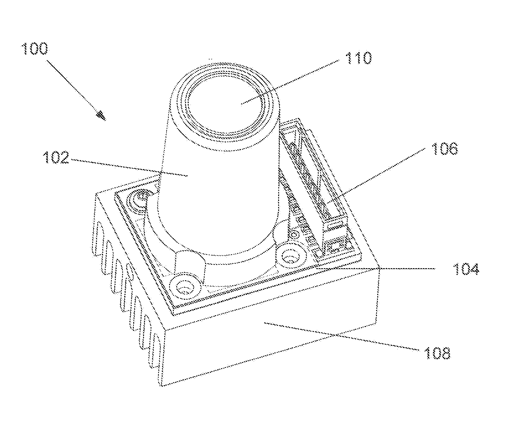
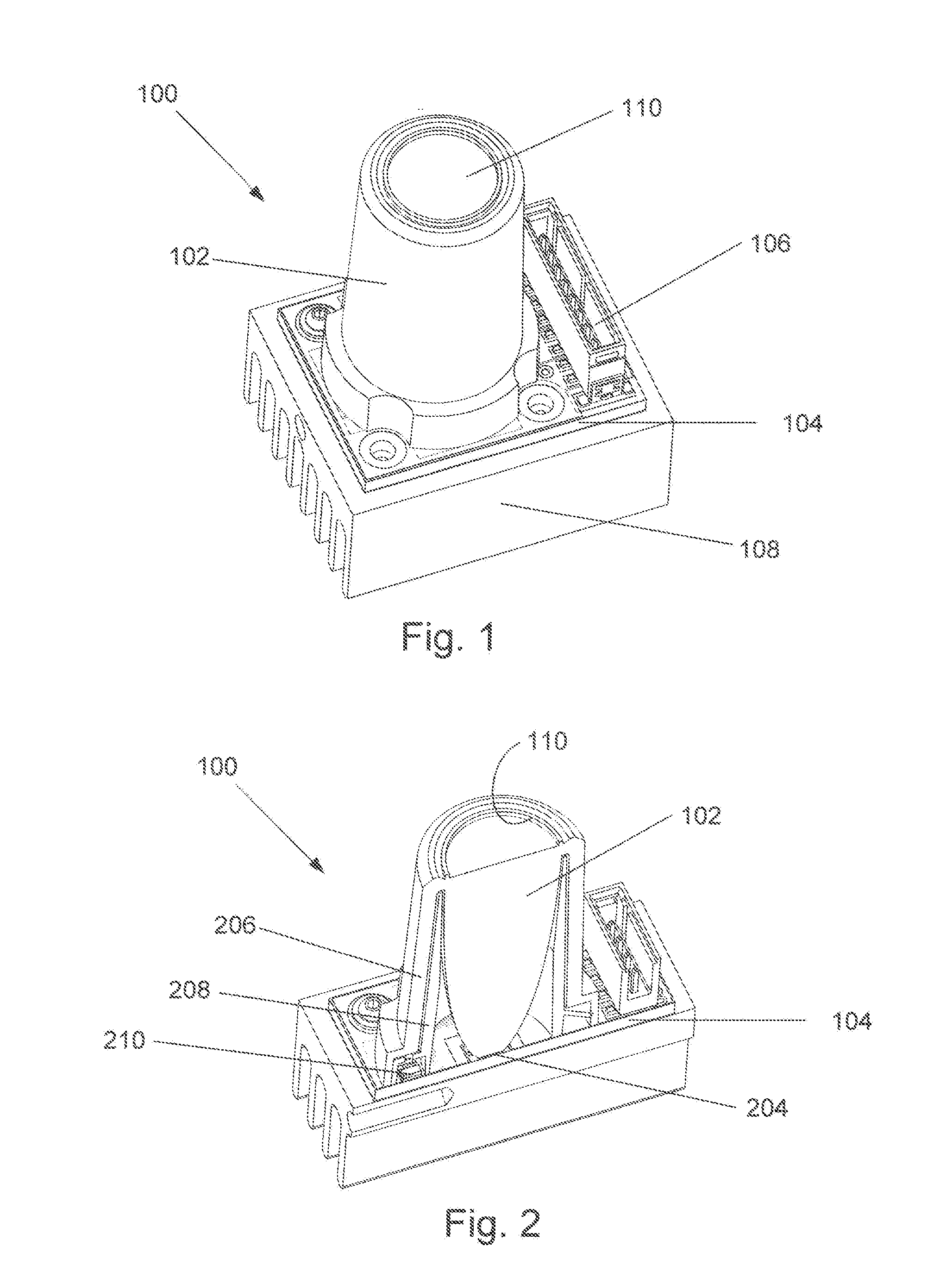
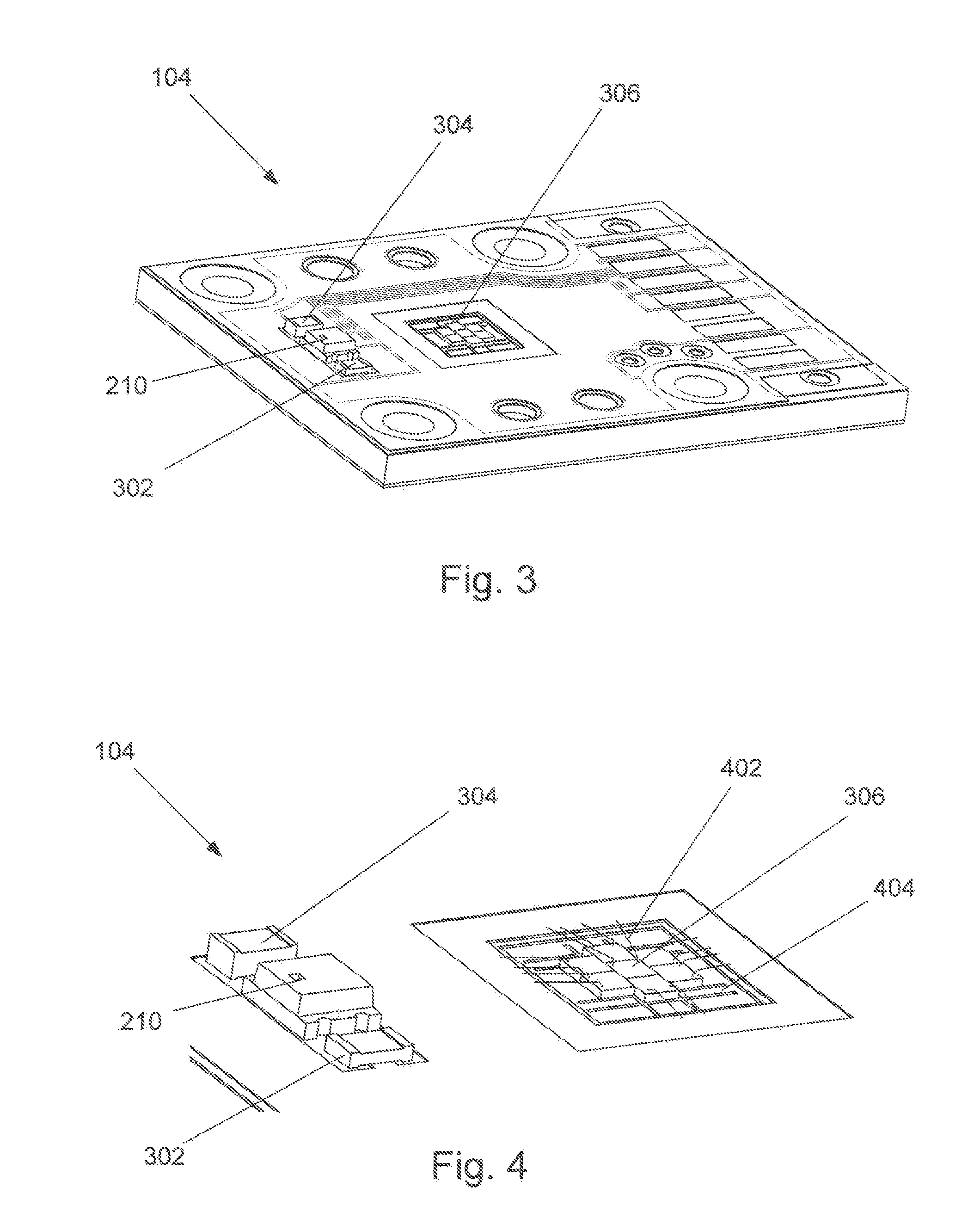
[0054]The present invention relates to Light Emitting Diode (LED) illumination systems for which the Etendue (area, solid angle, index squared product) is substantially preserved and has application across many markets including general illumination, fiber optic coupling including microscopes, endoscopes and boroscopes, machine vision and inspection, ultra-violet (UV) curing, medical illumination, projection systems and fluorescence illumination. In particular the present invention offers higher performance in a more readily manufactured and reliable package in comparison to prior art. An important aspect of the invention is the way the associated collection optic provides a sampling of the light from the LED die, die array or phosphor emitted at the entrance aperture of the optic and passing out the upper portion of the said optic and is then reflected by total internal reflection (TIR) back down the outer wall of the optic toward a photosensor attached to the same LED board. In th...


PUM


Abstract

An LED light engine system that incorporates light emitting diodes (LEDs) with one or more distinct colors, including broad band white light obtained from phosphors or a combination of LED die colors and LED die coated phosphors. The LED die or die arrays are mounted to a high thermal conductivity circuit board comprising COB technology which can include both the LED die and electronic drive components resulting in a compact and reliable design with improved thermal and optical performance. High efficiency non-imaging collection optics are coupled to the LEDs to efficiently capture substantially all of the light which they emit and reformat it as an output with substantially the same éntendue as that of the LED to provide high brightness sources. Feedback from the output back to a photosensor on the circuit board is provided to assure that the output of the collection optic remains constant.

Description

CROSS REFERENCE TO RELATED APPLICATION[0001]This application claims the benefit of priority from U.S. Provisional Patent Application No. 61 / 222,499 entitled LIGHT EMITTING DIODE LIGHT ENGINE which was filed on Jul. 2, 2009 in the name of Thomas J. Brukilacchio, the entire contents of which are incorporated herein by reference.FIELD OF THE INVENTION[0002]This invention, in general, relates to the collection and monitoring of light emitted from high brightness light emitting diode (LED) die or die arrays coupled into dielectric non-imaging optics and directed toward a monitoring photodiode. Applications cover many markets including commercial, military and industrial illumination where high brightness illumination is required, coupling to optical fibers such as in endoscope, boroscope or microscope illumination, uniform illumination for machine vision, general illumination as in recessed lights, fluorescence imaging, and UV Curing.BACKGROUND OF THE INVENTION[0003]High brightness light...

Claims


Application Information

Patent Timeline
Patent Type & Authority Applications(United States)
IPC IPC(8): H05B37/02
CPCF21K9/00F21V23/005F21Y2101/02F21V23/0457A61B2019/521G02B6/4206A61B1/0684A61B1/0692A61B1/07F21Y2113/005A61B2090/309F21Y2115/10F21Y2113/13
Inventor BRUKILACCHIO, THOMAS J.
Owner INNOVATIONS & OPTICS
Why Eureka
Try Eureka