RF printing rectifier using roll to roll printing method

Inactive Publication Date: 2011-01-20
PARU
View PDF6 Cites 4 Cited by
  • Summary
  • Abstract
  • Description
  • Claims
  • Application Information

AI Technical Summary

Benefits of technology

[0026]Since the RF printed rectifier according to the present invention is manufactured using a roll to roll printing process and a 100% printing proce

Problems solved by technology

However, this rectifier, based on silicon and inorganic oxides, is problematic in that

Method used


Image

  • RF printing rectifier using roll to roll printing method
  • RF printing rectifier using roll to roll printing method
  • RF printing rectifier using roll to roll printing method

Examples


example 1

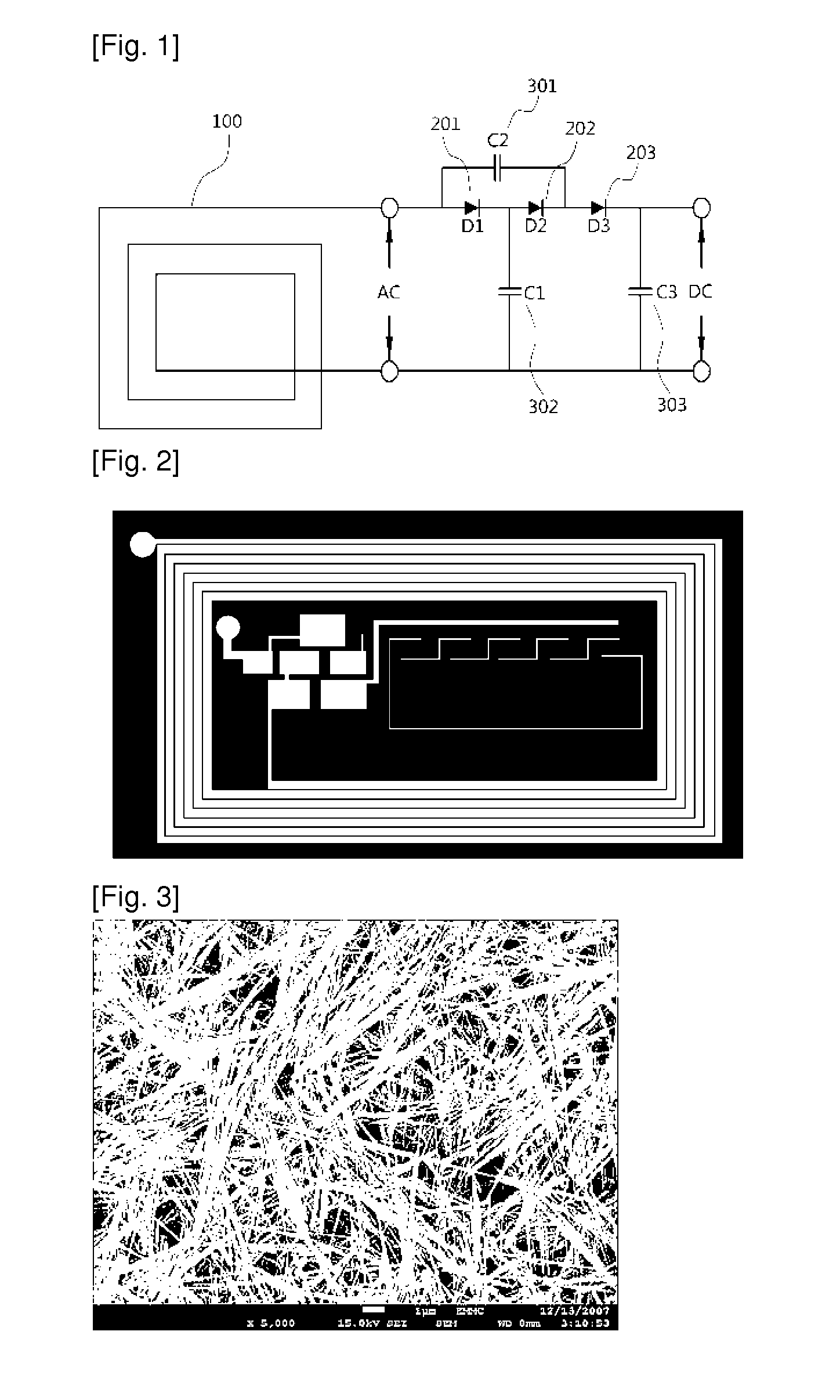
[0055]Zinc acetate (2.66 mol) and cobalt acetate (0.13 mol) were put into a reactor, trioctylamine (25 ml) was added thereto to form a mixture, and then the mixture was stirred in a supercritical state at a reaction temperature of 310° C. for 30 minutes to form a green material on the wall surface of the reactor. This green material was a zinc oxide nanowire doped with cobalt. Subsequently, the green zinc oxide nanowire is added and dispersed in ethanol to form a dispersion solution, and then a solvent and a finally-synthesized zinc oxide nanowire doped with cobalt were separated from the dispersion solution using a centrifugal separator. FIG. 3 is a scanning electron microscope photograph of the synthesized zinc oxide nanowire.

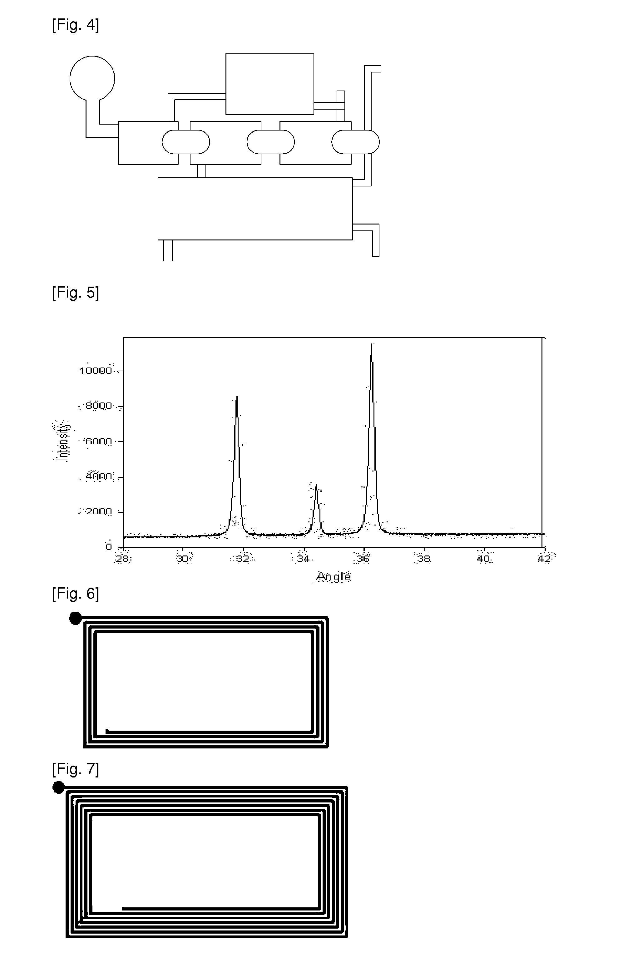
[0056]FIG. 5 is a graph showing the results of X-ray diffraction analysis of the zinc oxide nanowire. The separated zinc oxide nanowire doped with cobalt was powdered. The separated zinc oxide nanowire doped with cobalt was mixed with polyaniline at a mixing ...

example 2

[0057]After Bi nanocrystals in which As(SiMe3)3 and GaCl3 are dissolved in trioctylamine (TOA) were provided, Bi(III)2-ethylhexanoate was dissolved in dioctyl ether and trioctylphosphine (TOP) to form a mixed solution, and then NaBH4 dissolved in ethylenediamine added to the mixed solution, and thus Bi nanocrystals were deposited by an insoluble solvent. In order to grow the deposited Bi nanocrystals into GaAs nanowires, reactants of As(SiMe3)3 8.6 μL, Bi nanocrystal 1.7 mg, toluene 300 μL, oleic acid 24 Ml and Trioctly amine 850 μL were added to a hot solution (340° C.) in which GaCl3 14.3 mg and myristic acid 5.6 mg were dissolved in trioctylamine (TOA) 2.5 mL and then stirred in a glove box charged with nitrogen. In this case, the temperature of the resulting solution was decreased to a temperature of 40° C., but the resulting solution was heated to a temperature of 340° C. and then further stirred for 5 minutes to grow GaAs nanowires.

example 3

[0058]InCl3 18 mg, As(SiMe3)3 8.6 μL, Bi nanocrystal 1.7 mg, toluene 300 μL, oleic acid 24 μL and trioctyl amine 850 μL were added to a hot solution (340° C.) in which myristic acid 5.6 mg was dissolved in trioctylamine (TOA) 2.5 mL and then stirred in a glove box charged with nitrogen. In this case, the temperature of the resulting solution was decreased to a temperature of 40° C., but the resulting solution was heated to a temperature of 340° C. and then further stirred for 5 minutes to grow InAs nanowires.


PUM


Abstract

Disclosed herein is an RF printed rectifier manufactured using a roll to roll printing process, comprising: a printed antenna manufactured using conductive ink through the roll to roll printing process; a printed diode manufactured using the conductive ink through the roll to roll printing process; and a printed capacitor manufactured using the conductive ink through the roll to roll printing process, wherein an alternating current is input through the printed antenna, and a direct current is output through the printed diode and capacitor.

Description

TECHNICAL FIELD[0001]The present invention relates to a radio frequency (RF) printed rectifier using a roll to roll printing process and a method of manufacturing the same, and, more particularly, to a radio frequency (RF) printed rectifier manufactured using conductive ink, semiconductor ink, dielectric ink and conductor ink through a roll to roll printing process and a method of manufacturing the same.BACKGROUND ART[0002]With the growth of the market for digital household electric appliances such as mobile phones, digital cameras, DVDs, PDPs, LCDs and the like, requirements for an apparatus and a process for manufacturing semiconductors and other precise electronic parts are increasingly changing. In addition to the fields of ICs, electronic parts and displays, even in the energy fields of donor-acceptor type organic solar cells, dye-sensitized solar cells including titanium oxides, zinc oxides and the like, and fuel cells, research into simplifying a production process and reduci...

Claims


Application Information

Patent Timeline
IPC IPC(8): H01Q1/00H01L21/18
CPCG06K19/07749H05K3/12H05K1/16B82Y30/00H01L29/86
Inventor CHO, GYOU JINKIM, JAE YOUNGLIM, NAM SOOKIM, JUN SOEKKANG, HWI WONLIM, CHAE MIN
Owner PARU
Why Eureka
Try Eureka