
Color correction material, film-forming composition, and optical filter

Inactive Publication Date: 2011-03-03
ADEKA CORP
View PDF2 Cites 4 Cited by
  • Summary
  • Abstract
  • Description
  • Claims
  • Application Information

AI Technical Summary

Benefits of technology

[0016]Accordingly, an object of the present invention is to provide an optical filter that has sharp light absorption particularly at wavelengths ranging from 480 to 500 nm and that has excellent lightfastness, heat resistance, and moisture-and-heat resistance even in a system having an adhesive layer.Means for Solving the Problems
[0035]The present invention can provide an optical filter having excellent lightfastness, heat resistance, and moisture-and-heat resistance. The optical filter is suitable for improving display quality of image display devices and preventing glare of external light.

Problems solved by technology

Such a process, however, results in high cost because of the many steps involved in production and also has difficulty in making the optical filters thin.
It is, however, difficult to prevent the colorant compounds in the adhesive layers from causing degradation due to light, heat, etc., and there still is no optical filter that can ensure sufficient optical properties.
However, nothing has been suggested about the use of such color materials or colored composites in optical filters or about improvement of moisture-and-heat resistance of optical filters by using such color materials or clay mineral composites.
However, it describes nothing about using the cyanine compound in combination with a clay mineral or about using the cyanine compound by forming it into a clay mineral composite.

Method used


Image

  • Color correction material, film-forming composition, and optical filter
  • Color correction material, film-forming composition, and optical filter
  • Color correction material, film-forming composition, and optical filter

Examples


example 1-1

Synthesis of Clay Mineral Composite 1

[0139]40 g of a dispersion liquid prepared by dispersing 1.0 g of “Lucentite SAN210-A” (layered clay mineral (D); oleophilic smectite; product of Co-op Chemical Co., Ltd.) in 39 g of methylethyl ketone was mixed with 15 g of a solution prepared by dissolving 0.15 g of a hexafluorophosphate of Compound No. 1 (cyanine cation (A)) in 14.85 g of methylethyl ketone, and the mixture was stirred for 1 hour, to ion-exchange a portion of the organic cations (F), i.e., the interlayer ions of “Lucentite SAN210-A”, with Compound No. 1 (cyanine cation (A)). To this solution was added 150 ml of methanol, and the precipitated solid was filtered and separated, washed with water, and cleaned with methanol, to obtain 0.72 g of Clay Mineral Composite 1.

example 1-2

Synthesis of Clay Mineral Composite 2

[0140]The same process as in Example 1-1 was employed except that 0.3 g of a hexafluorophosphate of Compound No. 1 (cyanine cation (A)) was used, to obtain 0.70 g of Clay Mineral Composite 2.

example 1-3

Synthesis of Clay Mineral Composite 3

[0141]The same process as in Example 1-1 was employed except that 0.03 g of a hexafluorophosphate of Compound No. 2 (cyanine cation (A)) was used, to obtain 0.14 g of Clay Mineral Composite 3.


PUM

PropertyMeasurementUnit
Compositionaaaaaaaaaa
Oleophilicityaaaaaaaaaa

Abstract

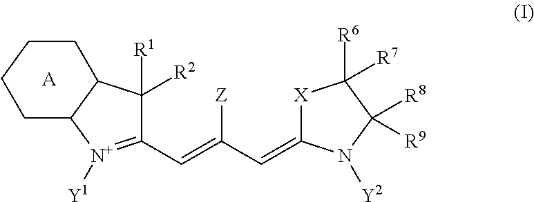
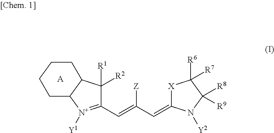
A color correction material contains at least one type of cyanine compound composed of a cyanine cation represented by general formula (I) below (wherein the symbols are as defined in the description) and a q-valent anion represented by pAnq− (wherein the symbols are as defined in the description), and at least one type of layered clay mineral; or a color correction material containing a clay mineral composite obtained by intercalating a cyanine cation represented by general formula (I) below, or preferably the cyanine cation and an organic cation, into a layered clay mineral. Also described is a film-forming composition containing the color correction material and an optical filter having a layer composed of the film-forming composition.Ring A represents a benzene ring or a naphthalene ring; X represents CR3R4, NR5, an oxygen atom, a sulfur atom, or a selenium atom.

Description

TECHNICAL FIELD[0001]The present invention relates to a color correction material containing a specific colorant compound and a layered clay mineral, a color correction material containing an inorganic-organic composite obtained by intercalating a specific colorant cation and an organic cation into a layered clay mineral, a film-forming composition obtained by blending the color correction material with a binder resin, and an optical filter having a layer composed of the film-forming composition. The optical filter is useful particularly as optical filters for image display devices.BACKGROUND ART[0002]Compounds having strong light absorption at specific wavelengths are used in recording layers of optical recording media such as CD-Rs, DVD-Rs, DVD+Rs, and blue laser recording discs and in optical elements of image display devices such as liquid crystal displays (LCDs), plasma display panels (PDPs), electroluminescence displays (ELDs), cathode-ray tube displays (CRTs), fluorescent dis...

Claims


Application Information

Patent Timeline
IPC IPC(8): G02B5/23
CPCC08K5/0091C08K5/34C08K5/46C08K5/56C09B23/0066G02B5/223C09B23/06C09B23/083C09B23/086C09B45/20C09B63/00C09B23/04
Inventor ISHIDA, TATSUYAYANAGISAWA, SATOSHIMAEDA, YOSUKE
Owner ADEKA CORP
Learn More