
Method of recycling scrap magnet

a scrap magnet and magnet technology, applied in the field of scrap magnet recycling, can solve the problems of scrap magnet generation, poor sintering, poor molding, etc., and achieve the effect of advantageously improving the magnetic properties of the recycled sintered magnet and further enhancing the productivity

Inactive Publication Date: 2011-03-03
ULVAC INC
View PDF14 Cites 17 Cited by
  • Summary
  • Abstract
  • Description
  • Claims
  • Application Information

AI Technical Summary

Benefits of technology

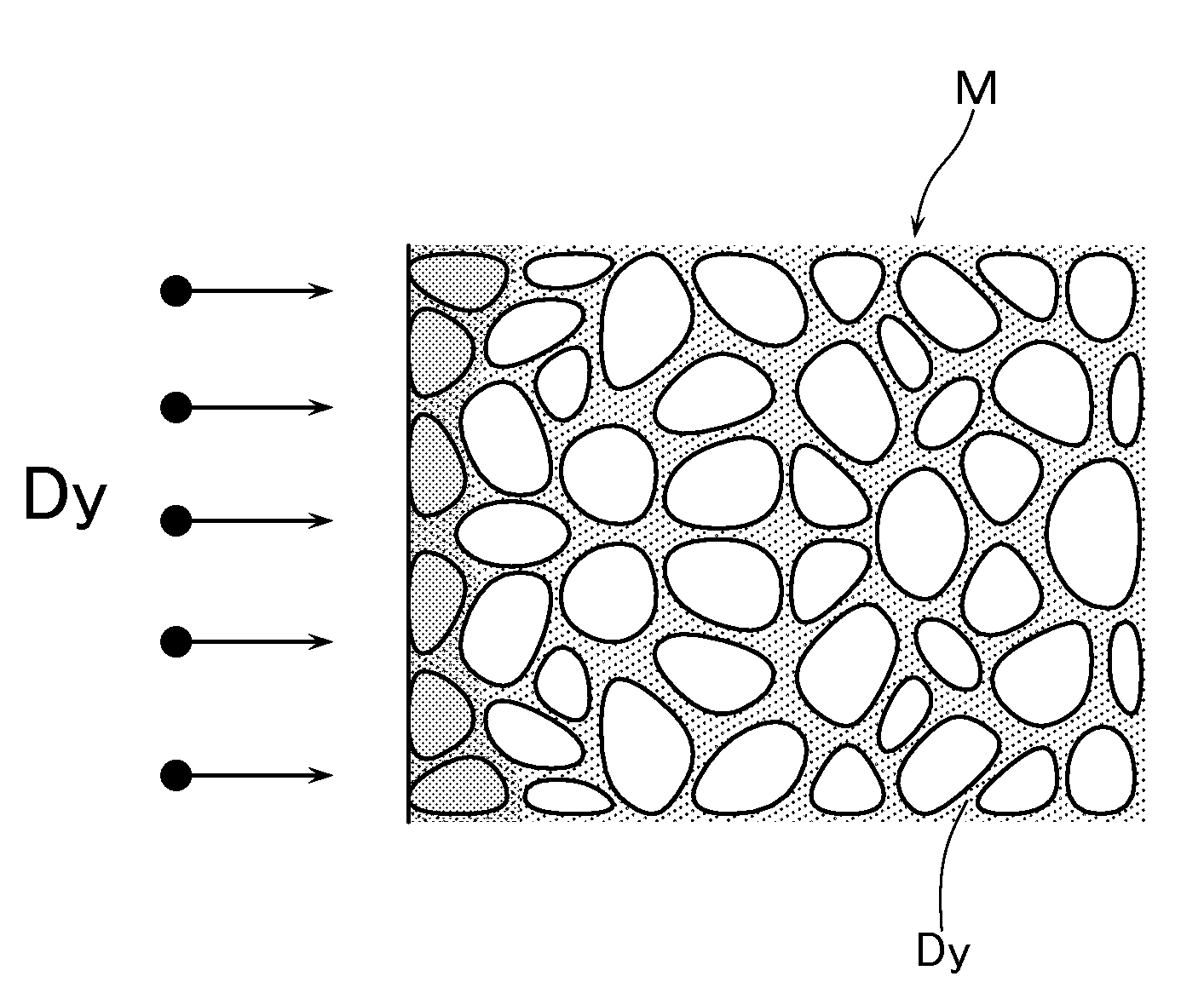
[0016]According to this arrangement, as a result of diffusion and uniform distribution of Dy and / or Tb into the grain boundary and / or grain boundary phase of the sintered body, there can be obtained a high-performance recycled magnet which has a Dy-rich and / or Tb-rich phase (phase containing Dy and / or Tb in a range of 5 to 80%) in the grain boundary and / or grain boundary phase, in which Dy and / or Tb is diffused only near the surface of the grain boundary, and in which magnetizing force and coercive force have effectively been recovered.
[0062]According to this table, in case the sintered bodies S were manufactured only from the scrap-derived recovered raw material powder, it can be seen that the coercive force was as low as 16.5 kOe, but that the coercive force improved to the level of 23.5 kOe when the sintered bodies were subjected to vacuum vapor processing. Further, it can be seen that the average values of the oxygen content increased by about only 20 ppm and that high-performance recycled magnets were obtained. Still furthermore, in case recycled magnets were manufactured by mixing molten raw material into the scrap-derived recovered raw material, it can be seen that the coercive force improved with an increase in the ratio of mixing the molten material, and also that the oxygen content can be reduced. As a result, it can be seen that the recycled magnets that were regenerated by applying this invention are also effective in further or repeated recycling.

Problems solved by technology

In the course of this kind of steps for manufacturing sintered magnets, scraps will be generated due to poor forming (poor molding), poor sintering and the like.
On the other hand, the sintered magnets have a Curie temperature of as low as about 300° C. as described above, and have a problem in that, depending on the conditions of the products in which the sintered magnets are employed, the sintered magnets will be demagnetized due to the heat.
Therefore, there is a problem in that magnets having a high coercive force cannot be obtained if the scrapped magnets are ground as they are for further recycling by a powder metallurgy method.
However, since in any one of the above-mentioned conventional examples the scrap magnets are recycled by undergoing a plurality of processing steps such as solvent extraction and the like as described above, there is a problem in that the productivity is poor and further that, since several kinds of solvents such as hydrofluoric acid and the like are used, a higher cost is incurred.

Method used


Image

  • Method of recycling scrap magnet
  • Method of recycling scrap magnet
  • Method of recycling scrap magnet

Examples


example 1

[0057]In Example 1, scrap magnets used in hybrid cars were recovered to thereby manufacture recycled magnets. The scrap magnets were manufactured from raw materials of industrial pure iron, metal neodymium, low-carbon ferroboron, and metal cobalt mixed in a mixing composition (% by weight) of 23Nd-6Dy-1Co-0.1Cu-0.1B-Bal.Fe. Further, since the recovered scrap magnets were subjected to surface treatment such as Ni plating and the like, a known peeling agent was used to peel the surface treatment layer (protection film) and the scrap magnets were then washed. Thereafter, the scraps were crushed or ground to a size of about 5 mm, whereby the scrap-derived recovered raw materials were obtained. Further, with industrial pure iron, metal neodymium, and low-carbon ferroboron as main raw materials, mixing composition (% by weight) of 24 (Nd+Pr)-6Dy-1Co-0.1Cu-0.1Hf-0.1Ga-0.98B-Bal.Fe was subjected to vacuum induction melting, and thin plate-shaped ingots (melted materials) of about 0.4 mm thi...


PUM

PropertyMeasurementUnit
Temperatureaaaaaaaaaa
Grain boundaryaaaaaaaaaa

Abstract

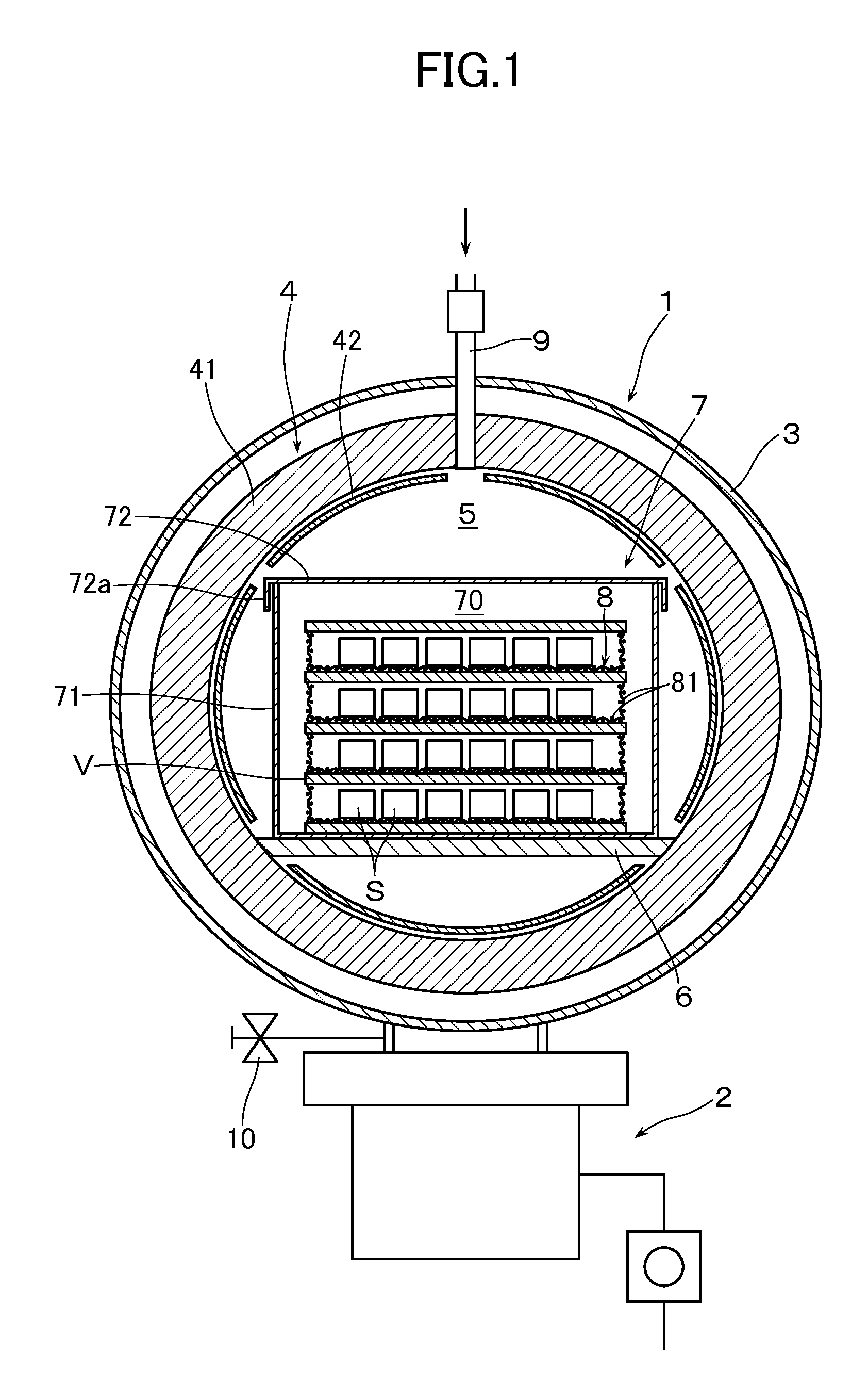
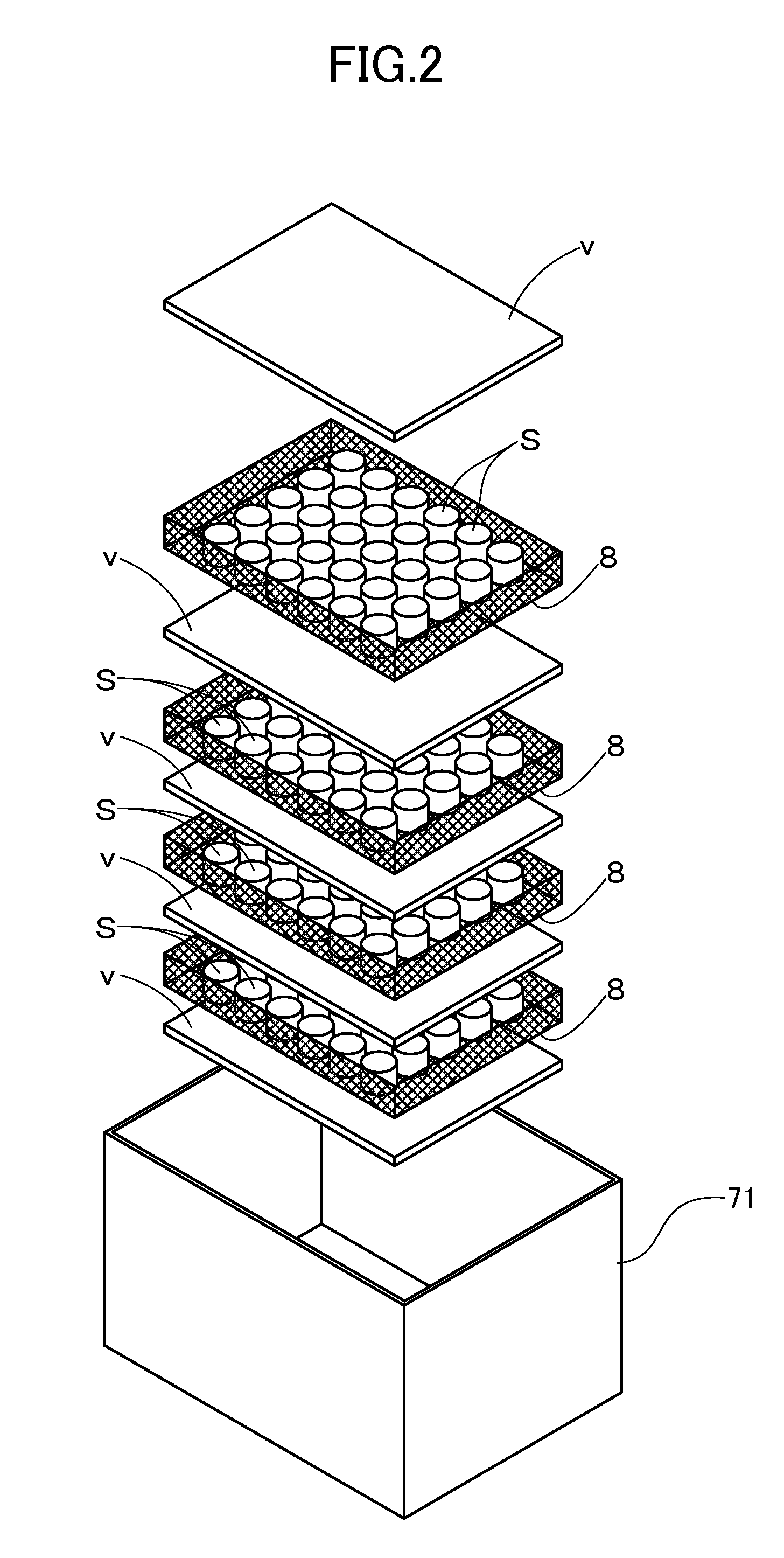
The method has the steps of: grinding a recovered scrap magnet which is an iron-boron-rare earth-based sintered magnet, thereby obtaining a scrap-derived recovered raw material powder; obtaining a sintered body from the scrap-derived recovered raw material powder by a powder metallurgy method; and processing the sintered body. The processing includes the steps of: heating the sintered body disposed in a processing chamber; evaporating a metal evaporating material containing at least one of Dy and Tb in which the metal evaporating material is disposed in the same or another processing chamber; adhering metal atoms evaporated in the evaporating step to a surface of the sintered body while controlling a supply amount of the evaporated metal atoms; and diffusing the adhered metal atoms into grain boundaries and / or grain boundary phases of the sintered body.

Description

[0001]This application is a national phase entry under 35 U.S.C. §371 of PCT Patent Application No. PCT / JP2009 / 052748, filed on Feb. 18, 2009, which claims priority under 35 U.S.C. §119 to Japanese Patent Application No. 2008-039299, filed Feb. 20, 2008, both of which are incorporated by reference.METHOD OF RECYCLING SCRAP MAGNET[0002]1. Technical Field[0003]The present invention relates to a method of recycling scrap magnets and relates, in particular, to a method of recycling scrap magnets in which: sintered magnets that have been once used or have been rejected in the course of a manufacturing step are recovered; and, without extraction by dissolution of specific elements out of the sintered magnets, the scrap magnets can be recycled into high-performance sintered magnets (permanent magnets).[0004]2. Background Art[0005]Nd—Fe—B-based sintered magnets (so-called neodymium magnets) can be manufactured at a low cost because they are made from a combination of iron and elements of Nd...

Claims


Application Information

Patent Timeline
IPC IPC(8): B05D5/00
CPCB22F3/24H01F41/0293B22F9/04B22F2003/241B22F2003/248B22F2998/10C22C33/0278C22C2202/02C23C10/06C23C14/16C23C14/5806H01F1/0577B22F8/00B22F3/10Y02W30/50Y02P10/20
Inventor NAGATA, HIROSHISHINGAKI, YOSHINORI
Owner ULVAC INC
Learn More