Photoelectric conversion device, photoelectric conversion device material, photosensor and imaging device

a conversion device and photoelectric technology, applied in the field of photoelectric conversion devices, can solve the problems of reducing the aperture ratio and the reduction of the light collection efficiency, and the failure of light to transmit through the color filter, and achieve the effect of excellent photoelectric conversion efficiency

Active Publication Date: 2011-03-31
FUJIFILM CORP
View PDF4 Cites 52 Cited by
  • Summary
  • Abstract
  • Description
  • Claims
  • Application Information

AI Technical Summary

Benefits of technology

[0046]According to the present invention, an organic photoelectric conversion device and a solid-st

Problems solved by technology

In this single-plate solid-state imaging device, since the color filter transmits only light at a limited wavelength, light failed in transmitting through the color filter is not utilized and the light utilization efficiency is bad.
Also, in recent years, fabrication of a multipixel device is proceeding, and the pixel size and in turn, the area of a photodiode part become small, which brings about problems of reduction in the aperture ratio and reduction in the light collection efficiency.
However, such a system is disadvantageous in that the color separation is poor, because the absorption range is overlapped among respective light-receiving parts in the depth direction of Si and the spectroscop

Method used


Image

  • Photoelectric conversion device, photoelectric conversion device material, photosensor and imaging device
  • Photoelectric conversion device, photoelectric conversion device material, photosensor and imaging device
  • Photoelectric conversion device, photoelectric conversion device material, photosensor and imaging device

Examples


example 1

Synthesis of Compound (5)

[0242]

(Synthesis of Compound 5a)

[0243]2,5-Dibromothiophene (produced by Tokyo Chemical Industry Co., Ltd.) (3.0 ml) was dissolved in 100 ml of dehydrated THF, and the solution was adjusted to an inner temperature of −78° C. in a dry ice bath. Subsequently, 19.2 ml of n-BuLi was slowly added dropwise and after 5 minutes, 5.1 ml of dehydrated DMF was gradually added dropwise. Thereafter, the dry ice bath was removed, and the inner temperature was raised to room temperature. After adding 2 N HCl, extraction with ethyl acetate was performed, and the oil layer was washed with 1 N HCl and aq. NaCl, then dried over sodium sulfate and filtered. The obtained reaction mixture was separated on a silica gel column (developing solution: AcOEt / n-Hexane=1 / 4), and the solvent was distilled off to obtain 1.3 g of Compound (5a).

(Synthesis of Compound 5B)

[0244]Compound (5a) (1.0 g), 1.8 g of diphenylamine (produced by Tokyo Chemical Industry Co., Ltd.), 3.4 g of cesium carbona...

example 2

Synthesis of Compound (8)

[0251]Compound (8) was synthesized by the same synthesis method as that for Compound (5) except for changing diphenylamine to 1,2′-dinaphthylamine (produced by Tokyo Chemical Industry Co., Ltd.).

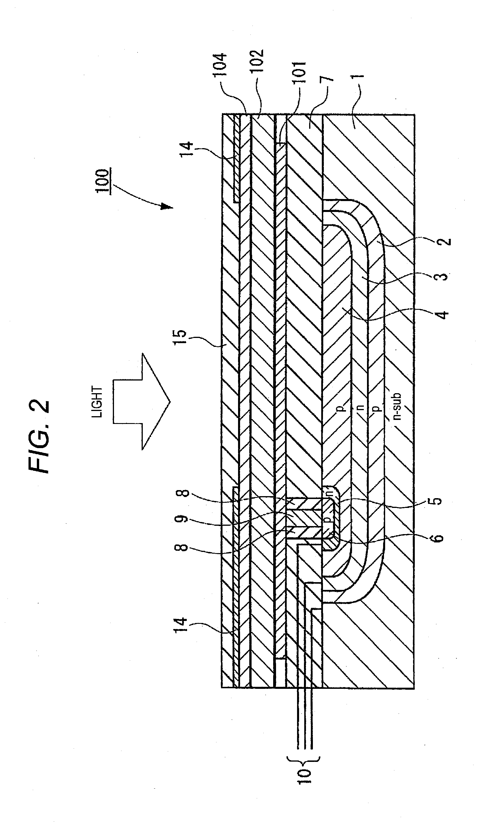
[0252]A solid-state imaging device was fabricated in the same manner as in Example 1 except for changing Compound (5) in the photoelectric conversion layer 12 to Compound (8).

example 3

Synthesis of Compound (18)

[0253]Compound (18) was synthesized by the same synthesis method as that for Compound (5) by using 2,5-dibromothieno[3,2-b]thiophene (produced by Tokyo Chemical Industry Co., Ltd.) as the starting material. The compound was identified by 1H-NMR.

[0254]1H-NMR (CDCl3) δ: 6.65 (1H, s), 7.26-7.43 (10H, m), 7.65 (2H, m), 8.00 (1H, s), 8.07 (2H, m), 8.23 (1H, br), 8.39 (2H, d).

[0255]Molecular weight: 513.63

[0256]The peak wavelength of the absorption spectrum and the molar extinction coefficient thereof were determined by the same operation as in Example 1, as a result, the peak wavelength of the absorption spectrum was 536 nm and the molar extinction coefficient at this wavelength was 94,000 M−1cm−1.

[0257]A solid-state imaging device was fabricated in the same manner as in Example 1 except for changing Compound (5) in the photoelectric conversion layer 12 to Compound (18).


PUM


Abstract

A photoelectric conversion device comprising an electrically conductive film, an organic photoelectric conversion film, and a transparent electrically conductive film, wherein the organic photoelectric conversion film contains a compound represented by the following formula (1) and an n-type organic semiconductor:
    • wherein each of R1 and R2 independently represents a substituted aryl group, an unsubstituted aryl group, a substituted heteroaryl group or an unsubstituted heteroaryl group, each of R3 to R11 independently represents a hydrogen atom or a substituent provided that an acidic group is excluded, m represents 0 or 1, n represents an integer of 0 or more, R1 and R2, R3 and R4, R3 and R5, R5 and R6, R6 and R8, R7 and R8, R7 and R9, or R10 and R11 may be combined each other to form a ring, and when n is an integer of 2 or more, out of a plurality of R7's and R8's, a pair of R7's, a pair of R8's, or a pair of R7 and R8 may be combined each other to form a ring.

Description

BACKGROUND OF THE INVENTION[0001]1. Field of the Invention[0002]The present invention relates to a photoelectric conversion device, a photoelectric conversion device material, a photosensor and an imaging device.[0003]2. Description of the Related Art[0004]Conventional photosensors in general are a device fabricated by forming a photodiode (PD) in a semiconductor substrate such as silicon (Si). As for the solid-state imaging device, there is widely used a flat solid-state imaging device where PD are two-dimensionally arrayed in a semiconductor substrate and a signal according to a signal charge generated by photoelectric conversion in each PD is read out through a CCD or CMOS circuit.[0005]The method for realizing a color solid-state imaging device is generally fabrication of a structure where on the light incident surface side of the flat solid-state imaging device, a color filter transmitting only light at a specific wavelength is disposed for color separation. In particular, a si...

Claims


Application Information

Patent Timeline
IPC IPC(8): H01L51/46H03K17/78C07D333/20C07D409/04C07D495/02C07D403/06
CPCB82Y10/00H01L27/307H01L51/0046H01L51/0053H01L51/006H01L51/42H01L51/0068H01L51/0072H01L51/0074H01L51/4253Y02E10/549H01L51/0061C07D333/36C07D333/56C07D333/72C07D409/04C07D409/06C07D409/12C07D495/04C07D495/14C09B23/105C09B57/008C09B3/00H10K39/32H10K85/211H10K85/621H10K85/636H10K85/633H10K85/655H10K85/6572H10K85/6576H10K30/30H10K30/00
Inventor YOFU, KATSUYUKINOMURA, KIMIATSUHAMANO, MITSUMASAMITSUI, TETSURO
Owner FUJIFILM CORP
Why Eureka
Try Eureka