Reducing carbon dioxide to products

a carbon dioxide and product technology, applied in the field of chemical reduction generally, can solve the problems of changing the ph of the ocean and other potentially damaging effects, the stability of the system used in the process, and the previous work in the field has many limitations, so as to stabilize the long-term reduction of carbon dioxide, reduce the cost, and improve the effect of stability

Inactive Publication Date: 2011-05-19
LIQUID LIGHT
View PDF100 Cites 160 Cited by
  • Summary
  • Abstract
  • Description
  • Claims
  • Application Information

AI Technical Summary

Benefits of technology

[0009]The objects, features and advantages of the present invention include providing a method and / or apparatus for implementing reducing carbon dioxide to products that may (i) catalytically reduce carbon dioxide using steel cathodes or other low cost cathode materials, (ii) produce high faradaic yields (e.g., >20%), (iii) produce organic products with steel and nickel alloy cathodes at ambient temperature and pressure, (iv) provide stabile long-term reduction of carbon dioxide using copper-based alloy electrodes and / or (v) provide for commercialization of electrochemical carbon dioxide reduction.

Problems solved by technology

Research since the 1970s indicates increasing concentrations of carbon dioxide in the atmosphere may be responsible for altering the Earth's climate, changing the pH of the ocean and other potentially damaging effects.
Previous work in the field has many limitations, including the stability of systems used in the process, the efficiency of systems, the selectivity of the systems or processes for a desired chemical, the cost of materials used in systems / processes, the ability to control the processes effectively, and the rate at which carbon dioxide is converted.
No commercially available solutions for converting carbon dioxide to economically valuable fuels or industrial chemicals currently exist.
All systems developed to date have failed to make commercial systems for the reasons outlined above.
The systems developed in laboratories could not be scaled to commercial or industrial size because of various performance limitations.
Existing electrochemical and photochemical processes / systems have one or more of the following problems that prevent commercialization on a large scale.
In other processes, organic solvents were used that made scaling the process difficult because of the costs and availability of the solvents, such as dimethyl sulfoxide, acetonitrile and propylene carbonate.
However, the electrodes are quickly “poisoned” by undesirable reactions on the electrode and often cease to work in less than an hour.
A mix of products makes extraction and purification of the products costly and can result in undesirable waste products that must be disposed.
Much of the work done to date on carbon dioxide reduction is inefficient because of high electrical potentials utilized, low faradaic yields of desired products and / or high pressure operation.
The energy consumed for reducing carbon dioxide thus becomes prohibitive.
Many conventional carbon dioxide reduction techniques have very low rates of reaction.

Method used


Image

  • Reducing carbon dioxide to products
  • Reducing carbon dioxide to products
  • Reducing carbon dioxide to products

Examples


example 1

General Electrochemical Methods

[0061]Chemicals and materials. All chemicals used were >98% purity and used as received from the vendor (e.g., Aldrich), without further purification. Either deionized or high purity water (Nanopure, Barnstead) was used to prepare the aqueous electrolyte solutions.

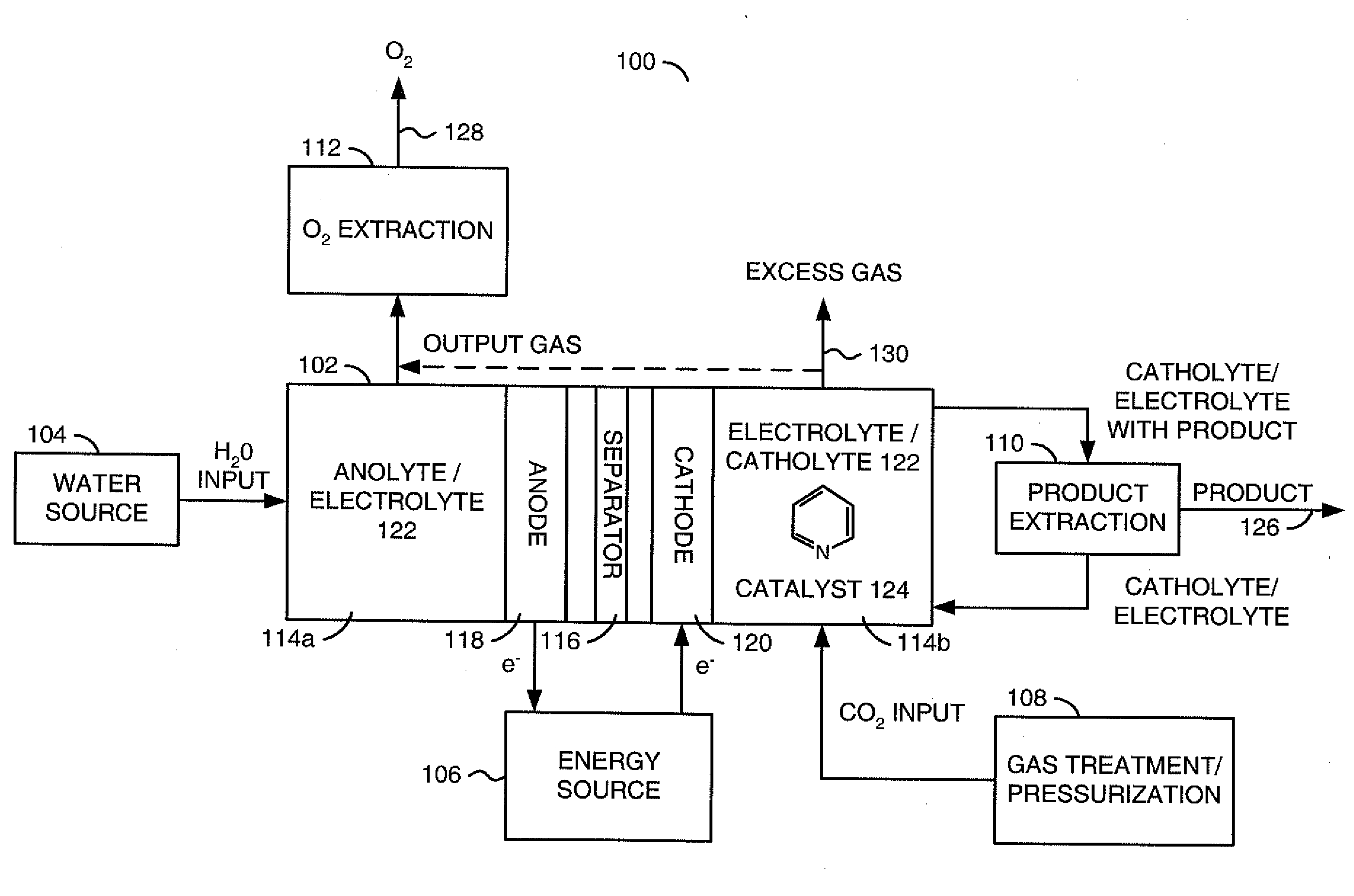
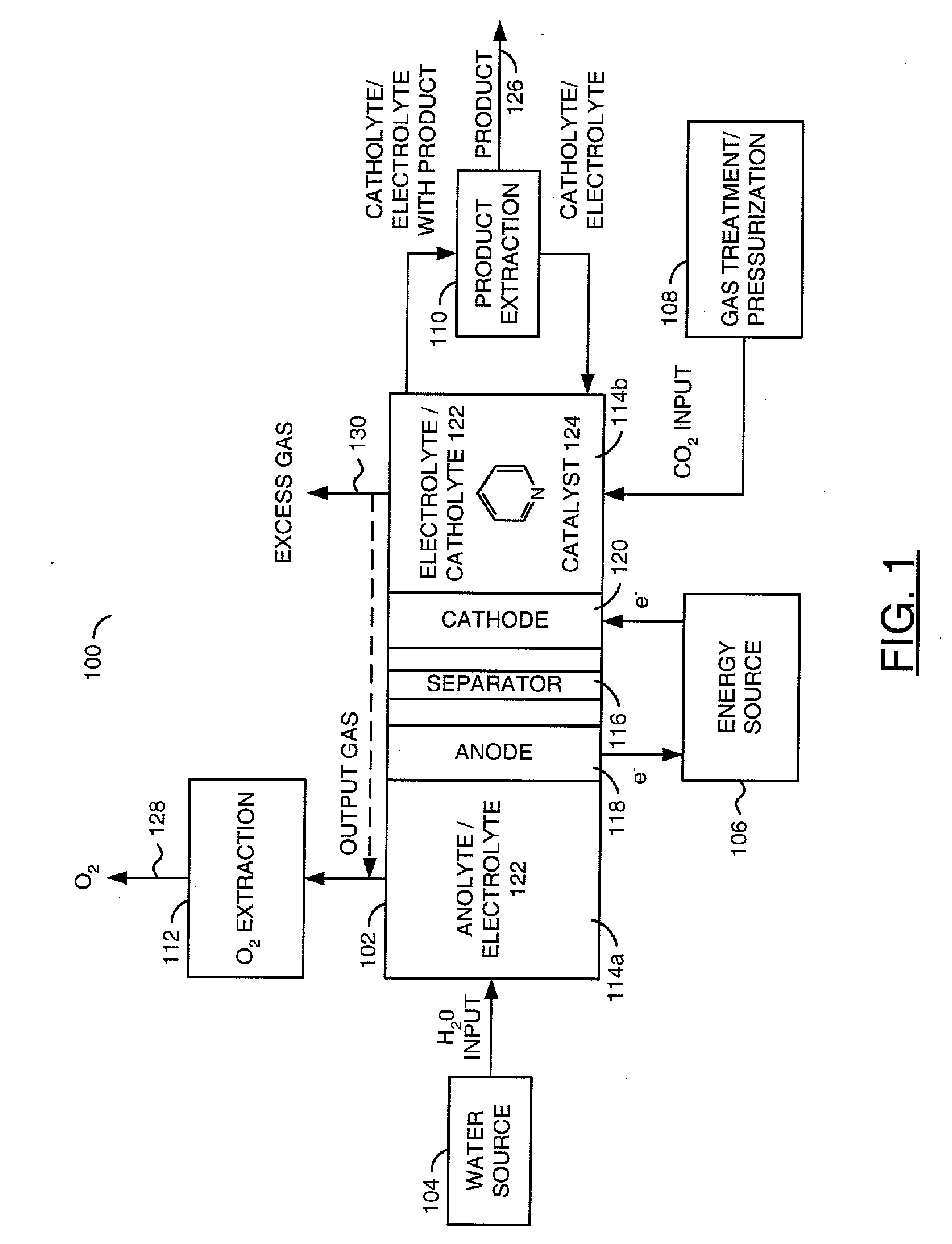
[0062]Electrochemical system. The electrochemical system was composed of a standard two-compartment electrolysis cell 102 to separate the anode 118 and cathode 120 reactions. The compartments were separated by a porous glass frit or other ion conducting bridge 116. The electrolytes 122 were used at concentrations of 0.1 M to 1 M, with 0.5 M being a typical concentration. A concentration of between about 1 mM to 1 M of the catalysts 124 were used. The particular electrolyte 122 and particular catalyst 124 of each given test were generally selected based upon what product or products were being created.

[0063]Referring to FIG. 7, a flow diagram of an example method 140 used in the electrochemica...

example 2

General Photoelectrochemical Methods

[0066]Chemicals and materials. All chemicals used were analytical grade or higher. Either deionized or high purity water (Nanopure, Barnstead) was used to prepare the aqueous electrolyte solutions.

[0067]Photoelectrochemical system. The photoelectrochemical system was composed of a Pyrex three-necked flask containing 0.5 M KCl as supporting electrolyte and a 1 mM to 1 M catalyst (e.g., 10 mM pyridine or pyridine derivative). The photocathode was a single crystal p-type semiconductor etched for approximately 1 to 2 minutes in a bath of concentrated HNO3:HCl, 2:1 v / v prior to use. An ohmic contact was made to the back of the freshly etched crystal using an indium / zinc (2 wt. % Zn) solder. The contact was connected to an external lead with conducting silver epoxy (Epoxy Technology H31) covered in glass tubing and insulated using an epoxy cement (Loctite 0151 Hysol) to expose only the front face of the semiconductor to solution. All potentials were ref...

example 3

Analysis of Products of Electrolysis

[0073]Electrochemical experiments were generally performed using a CH Instruments potentiostat or a DC power supply with current logger to run bulk electrolysis experiments. The CH Instruments potentiostat was generally used for cyclic voltammetry.

[0074]Electrolysis was run under potentiostatic conditions from approximately 6 hours to 30 hours until a relatively similar amount of charge was passed for each run.

[0075]Gas Chromatography. The electrolysis samples were analyzed using a gas chromatograph (HP 5890 GC) equipped with a FID detector. Removal of the supporting electrolyte salt was first achieved with an Amberlite IRN-150 ion exchange resin (cleaned prior to use to ensure no organic artifacts by stirring in a 0.1% v / v aqueous solution of Triton X-100, reduced (Aldrich), filtered and rinsed with a copious amount of water, and vacuum dried below the maximum temperature of the resin (approximately 60° C.) before the sample was directly injected...


PUM

PropertyMeasurementUnit
faradaic yieldaaaaaaaaaa
electrical potentialaaaaaaaaaa
temperaturesaaaaaaaaaa

Abstract

A method for reducing carbon dioxide to one or more products is disclosed. The method may include steps (A) to (C). Step (A) may bubble the carbon dioxide into a solution of an electrolyte and a catalyst in a divided electrochemical cell. The divided electrochemical cell may include an anode in a first cell compartment and a cathode in a second cell compartment. The cathode generally reduces the carbon dioxide into the products. Step (B) may vary at least one of (i) which of the products is produced and (ii) a faradaic yield of the products by adjusting one or more of (a) a cathode material and (b) a surface morphology of the cathode. Step (C) may separate the products from the solution.

Description

CROSS REFERENCE TO RELATED APPLICATIONS[0001]This application claims priority to U.S. Provisional Application Ser. No. 61 / 288,434, filed Dec. 21, 2009, U.S. Provisional Application Ser. No. 61 / 292,937, filed Jan. 7, 2010, and U.S. Provisional Application Ser. No. 61 / 315,692, filed Mar. 19, 2010, which are hereby incorporated by reference in their entirety.FIELD OF THE INVENTION[0002]The present invention relates to chemical reduction generally and, more particularly, to a method and / or apparatus for implementing reducing carbon dioxide to products.BACKGROUND OF THE INVENTION[0003]The combustion of fossil fuels in activities such as the electricity generation, transportation, and manufacturing produces billions of tons of carbon dioxide annually. Research since the 1970s indicates increasing concentrations of carbon dioxide in the atmosphere may be responsible for altering the Earth's climate, changing the pH of the ocean and other potentially damaging effects. Countries around the w...

Claims


Application Information

Patent Timeline
Patent Type & Authority Applications(United States)
IPC IPC(8): C25B3/04C25B1/00C25B3/25
CPCC25B1/003C25B3/04C25B1/55C25B3/25C25B1/23C25B11/046C25B9/19
Inventor COLE, EMILY BARTONSIVASANKAR, NARAYANAPPABOCARSLY, ANDREWTEAMEY, KYLEKRISHNA, NETY
Owner LIQUID LIGHT
Why Eureka
Try Eureka