Detector and Methods of Detecting

a detector and ultrasonic technology, applied in the direction of electrical/magnetic means, structural/machine measurement, geophysical measurements, etc., can solve the problems of increasing the number of sensors required to detect wear, gas leaks are and the narrowband test signal produced by the piezoelectric transducer is more susceptible to environmental extremes of temperature than the broadband pressurised leak signal. , to achieve the effect of simple construction and increased temperature stability

Active Publication Date: 2011-05-26
ROSEMOUNT MEASUREMENT
View PDF18 Cites 35 Cited by
  • Summary
  • Abstract
  • Description
  • Claims
  • Application Information

AI Technical Summary

Benefits of technology

[0029]According to some embodiments of the present invention there is provided an ultrasonic detector suitable for mounting in a position for surveying an area for a source of airborne ultrasound, which detector comprises a sensor for detecting an ultrasonic sound signal, characterised by a transducer configured or adapted to produce a broadband ultrasonic sound signal for reception by said sensor enabling said ultrasonic detector to perform a self-test. Preferably the self-test is performed by the detector whilst it is mounted in position. In some embodiments the self-test is a periodic forced test and in other embodiments the self-test is a periodic calibration check. In other embodiments, the detector is configured to perform both periodic forced tests and periodic calibration checks. By generating a broadband sound signal, the proper functioning of the detector can be checked over its entire frequency range, or a smaller part of it if preferred. Furthermore a broadband sound signal has a frequency spectrum that more closely resembles a real gas leak and is therefore a more reliable way to test the correct functioning of the detector. An additional advantage is obtained if the transducer is placed inside a housing of the detector: the transducer and the signal it produces during use are both shielded from the environment external to the detector. In this way changes in temperature and humidity in the external environment have a limited effect on the operation of the transducer and on the broadband ultrasonic sound signal, whereby the accuracy of the self-test is greatly improved.

Problems solved by technology

In the latter case the ultrasound is due to mechanical wear of bearings or stressed components for example.
However, when assemblies have multiple stress points the number of sensors required to detect wear can become prohibitive for cost reasons.
This characteristic has made gas leaks susceptible of detection.
Since the piezoelectric transducer and microphone are exposed to the environment, there is a problem of environmentally forced drift (explained in greater detail below), which may trigger a false alarm.
In particular, the narrowband test signal produced by the piezoelectric transducer is more susceptible to environmental extremes of temperature than the broadband pressurised leak signal to be detected.
As a result the test signal emitted by the piezoelectric transducer may fall outside the tolerance levels at point of detection, (causing fault alarms) even though the detector is still functioning well within the parameters of installation.
Operator confidence can be lost as a result which is undesirable.
A further problem with this first type of self-test is that mounting the test transducer on the outside of the enclosure results in a blind spot since it must protrude into the sensor's cone of sensitivity.
In particular, the background noise is used to check whether or not the receiver transducer of the detector is still operational; if the background noise is not detected the detector generates a fault alarm.
The problems with this are that the receiver transducer has to have a very low sensing threshold (otherwise the self-test will not work in quiet environments), and there is no alternative way for the operator to check functionality.
In summary, existing ultrasonic gas detectors have reliability problems as far as self-testing is concerned.
Another problem facing ultrasonic gas leak detectors is variation of air temperature and humidity between the source of the gas leak and the detector.
For example, it is possible that a gas leak which would have just triggered an alarm may fail to do so if the temperature has increased at the plant so that the sound pressure level at the detector now falls below the alarm threshold.
Both options are time consuming as the detectors are usually mounted several metres above ground level in order to achieve maximum sensing distances.
One problem with both of these methods is that site personnel are required to access the detectors, and on-site calibration can only be carried out during routine maintenance schedule.
Existing forms of fixed ultrasonic gas leak detector utilise a single sensing head due either to the cost of the sensor or the circuitry involved to achieve the necessary certification for use in hazardous areas.
Since there is no direct interaction between leaking gas and the detector it is currently not possible to determine which type of gas is leaking.
Furthermore due to the small amount of energy and the wavelengths within the sensing range, together with the nature of sound propagation through air, it is extremely difficult to ascertain the direction of the leak source using current detector design.
This is clearly costly for the plant operator and may not be necessary if the location of the leak and the associated process could be identified more accurately.
Installation of gas leak detectors gives rise to further problems.
One problem with this method is that the higher the background noise level, the smaller the detection range of the detector.
A further problem has been identified with this methodology: the background noise environment is dynamic.
Such spikes are often caused by faulty mechanical components in machinery or attenuation from audible alarm devices.
Such spikes can result in false alarms using existing detector functionality.
When used in harsh industrial environments (e.g. on an oil drilling rig) the sensing face must be shielded from the ingress of moisture and contaminants which means they can only be mounted facing downwards which severely restricts the sensing range.
A further disadvantage arises due to the use of different materials in the diaphragm and the components of the electro-magnetic field or components in the capacitor assembly and air gap.
At extreme temperatures the expansion and contraction rates of said different materials results in signal drift.
Microphone construction is also extremely complicated as the tolerances of the assembly need to be carefully controlled and construction must take place in a clean environment so that moisture and contaminants are eliminated during assembly, this leads to very expensive assembly costs.
At the aforementioned extremes of temperature, the relative contraction or expansion of each part has an undesired effect on the frequency response of the detector.

Method used


Image

  • Detector and Methods of Detecting
  • Detector and Methods of Detecting
  • Detector and Methods of Detecting

Examples


Embodiment Construction

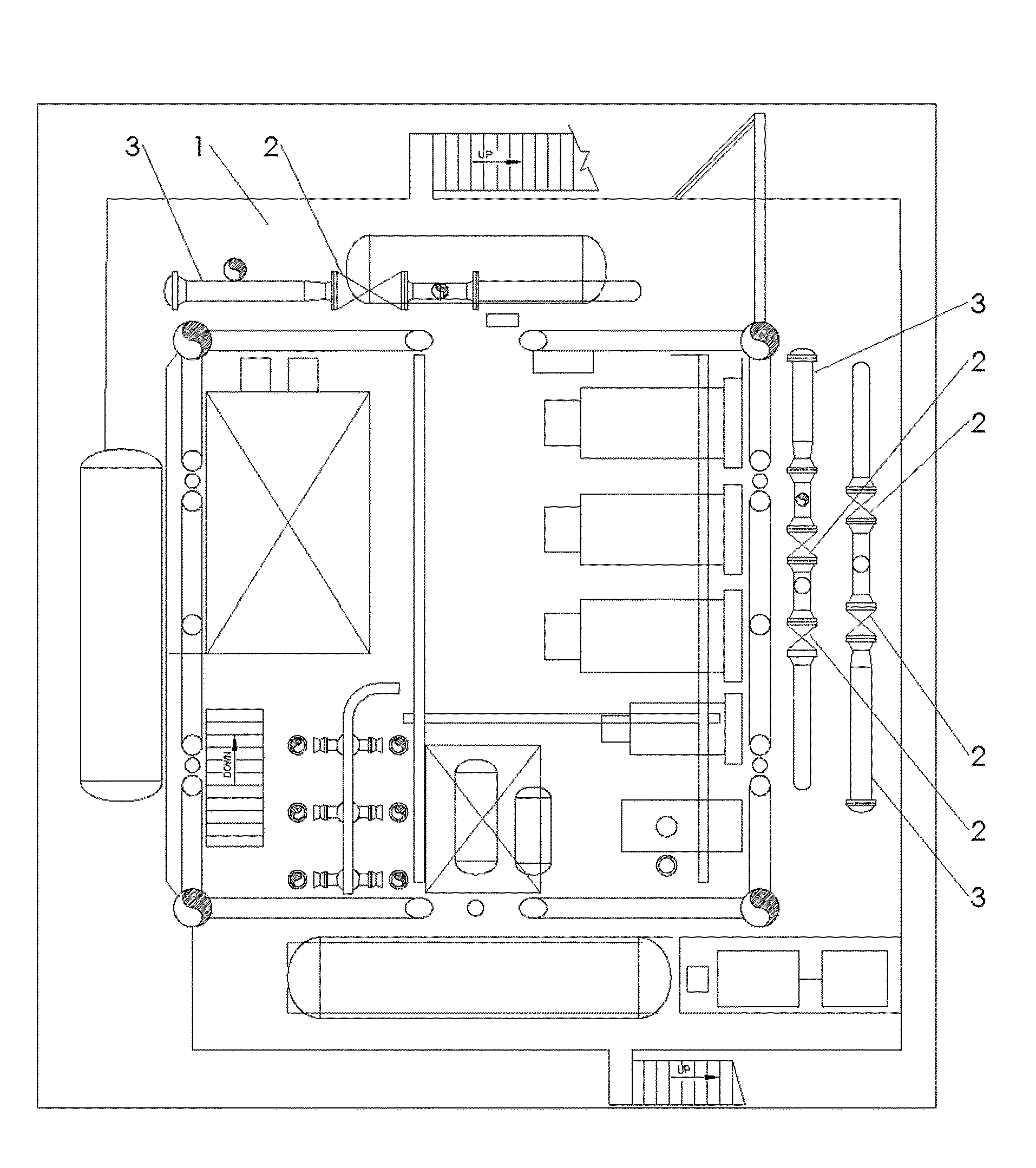
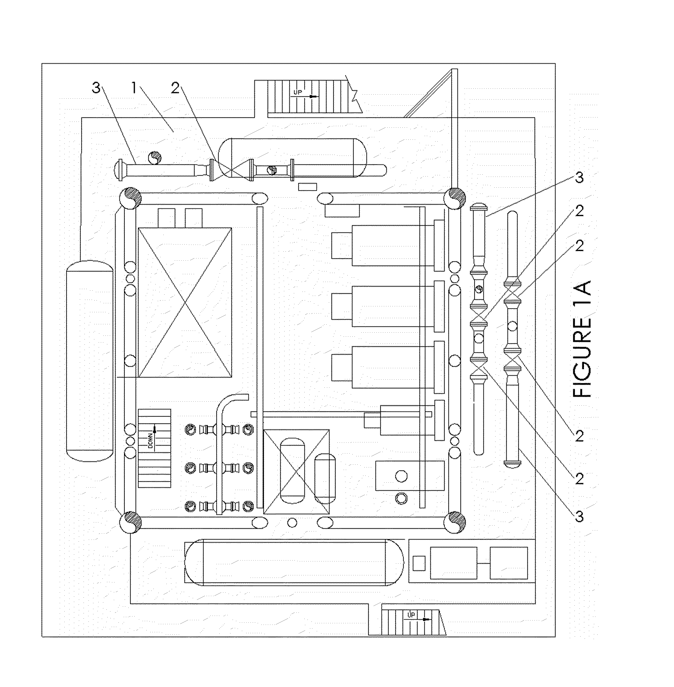
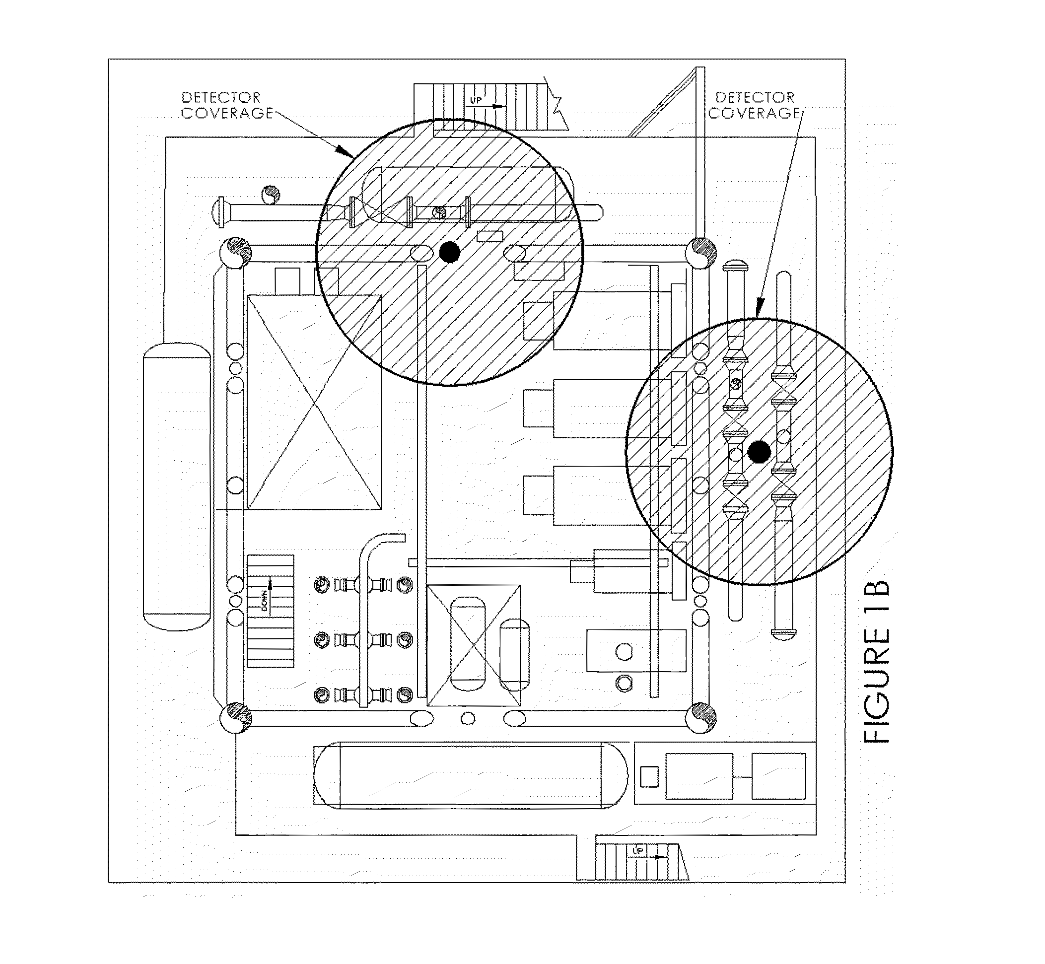
[0089]Referring to FIG. 1A a part of an industrial drilling plant generally identified by reference numeral 1 comprises multiple valve stations 2 between receiver pipe racks 3 and underground drilling heads (not shown). The valve stations 2 regulate input from the drilling heads (not shown) to the next process deck via pipe racks 3. As such the plant provides a pressure regulation function for gas (e.g. natural gas) between drilling heads and the process facility on the plant. It is important to monitor the valves and pipes for any leaks; such leaks could be a potential explosion hazard. FIG. 1B shows where two detectors have been mounted in the plant and their respective areas of coverage in which a gas leak can be detected. Any gas leaks that occur within the shaded areas in FIG. 1B can be detected and the appropriate alarms raised by the detectors.

[0090]Referring to FIGS. 2, 3 and 4 an ultrasonic gas leak detector generally identified by reference numeral 10 comprises a housing 1...


PUM

PropertyMeasurementUnit
ultrasonic frequencyaaaaaaaaaa
sound pressure levelaaaaaaaaaa

Abstract

An ultrasonic detector (10) suitable for mounting in a position for surveying an area for a source of airborne ultrasound, which detector comprises a sensor (20) for detecting an ultrasonic sound signal, characterised by a transducer (64) configured to produce a broadband ultrasonic sound signal for reception by said sensor (20) enabling said ultrasonic detector to perform a self-test.

Description

FIELD OF THE INVENTION[0001]The present invention relates to an ultrasonic detector for detecting airborne ultrasound and in certain aspects to an ultrasonic detector for detecting high-pressure gas leaks, to methods of surveying an area for a source of airborne ultrasound, to an ultrasonic sensor and to a detector comprising such a sensor.BACKGROUND OF THE INVENTION[0002]Many industrial operations, such as well drilling, oil production, oil refining and industrial gas production, utilise piping to move a wide variety of high-pressure fluids such as gas and liquids. The pipes move such fluids for operating and controlling industrial processes amongst other things. Frequently the fluids that are piped are potentially explosive and the piping requires careful monitoring for leaks; leaks are required to be identified quickly to enable the appropriate remedial action to be taken.[0003]Other industrial operations involving pressurised gas or those incorporating rotating parts may also pr...

Claims


Application Information

Patent Timeline
Patent Type & Authority Applications(United States)
IPC IPC(8): G01N29/30G01M3/24
CPCG01M3/243G01H11/08
Inventor ROSE, DARREN MICHAELHURREY, ROGER THOMAS
Owner ROSEMOUNT MEASUREMENT
Why Eureka
Try Eureka