
Sample Collection and Detection System

a detection system and sample technology, applied in the field of sample collection and detection system, can solve the problems of inability to take the detector system, the cost of the disclosed hand-portable sample collection device is relatively high, and the cost of these units limits the deployability, so as to achieve quick and effective separation

Inactive Publication Date: 2011-06-02
MICROSAIC SYST
View PDF13 Cites 35 Cited by
  • Summary
  • Abstract
  • Description
  • Claims
  • Application Information

AI Technical Summary

Benefits of technology

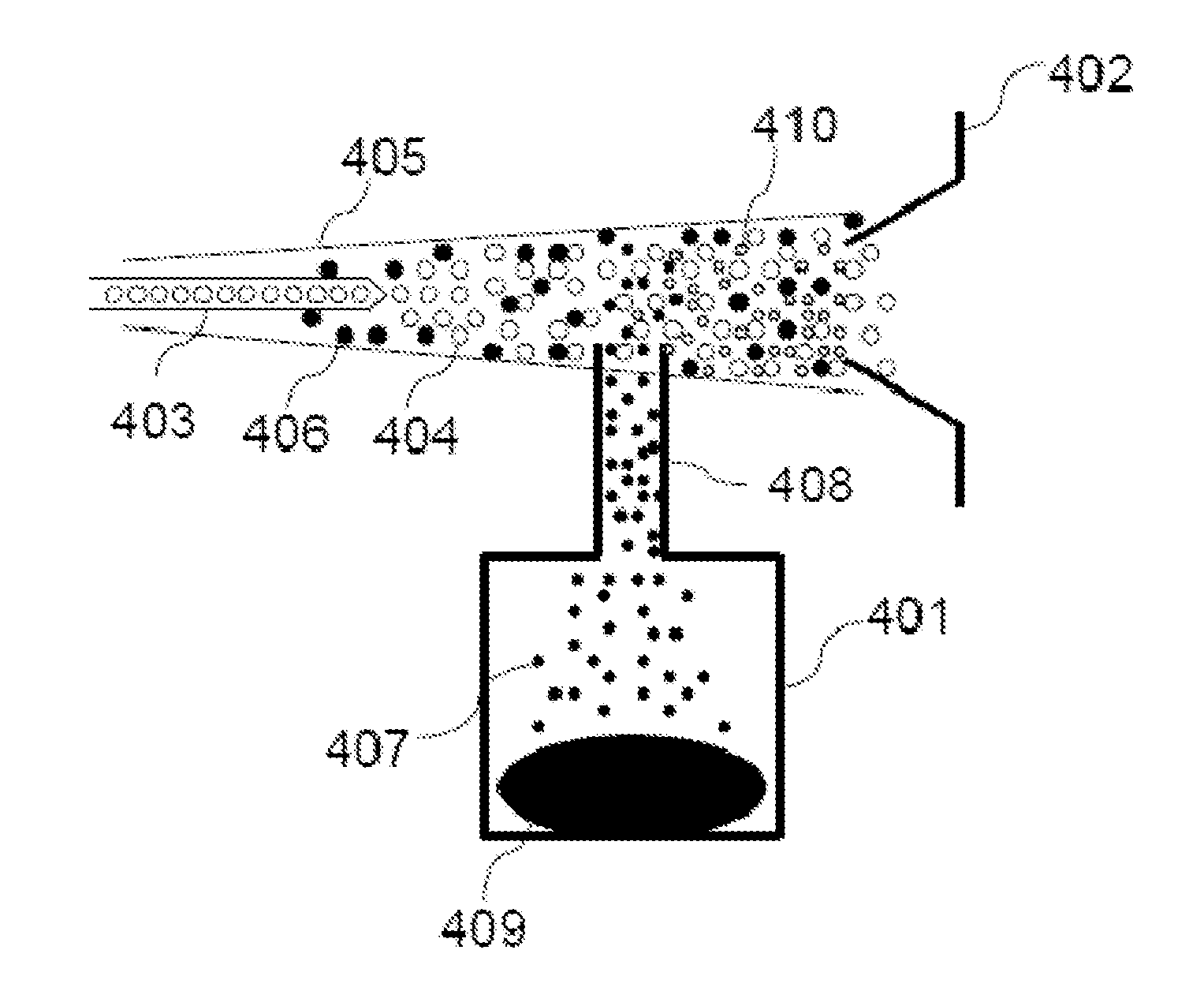
[0009]These and other problems are addressed by the present invention in providing a detection system that is configured for receipt of a solid sample and which through a heating of that sample effects a generation of vapours which through contact with a secondary ionisation source are ionised and then analysed by a mass spectrometer. The detection system may include a detachable sample collector which if provided allows for the remote collection of the sample to the place of analysis. The detachable sample collector device may be portable for remote sampling. By providing such an arrangement, it is possible to provide for a trapping of ambient samples remotely using a detachable sample collector and to bring the sample so trapped to the detector, rather than vice-versa. Such a system provides response rates that are sufficiently rapid so as to quickly and effectively separate the chemical constituents from a sample containing chemical interferents, and sufficiently selective so as to permit easy identification of chemical species of interest based on their molecular ions and without the need for spectral interpretation. In another arrangement the sample collector is an integral part of the system and the sample is brought to the sample collector as opposed to the other way around.
[0012]In a preferred embodiment, the secondary ionisation source is a secondary electrospray ionisation (SESI) source. In SESI, neutral molecules are ionised by ions emitted by an electrospray ionisation source (ESI). The neutral molecules may be entrained in a vapour, or in uncharged droplets from an aerosol spray. The neutrals interact with the electrospray and secondary electrospray ions are generated. The exact mechanism or mechanisms responsible for ionization of the analyte molecules by SESI remains unclear. There are two generally accepted ionization mechanisms: incorporation of the neutrals into the electrospray droplets; or gas-phase ion-molecule reactions with the electrospray-produced ions. The ESI may include a desolvation gas such as nitrogen or helium which may be used to direct secondary electrospray ions and neutrals to the inlet of the mass spectrometer detector. The mass spectrometer detector can be purely a mass spectrometer (MS) or may contain further elements that separate the neutrals or ions to improve the selectivity and sensitivity of the system.
[0014]In a first arrangement the sample collection chamber is configured for receipt of a swipe or wipe with is useable to collect trace elements of the sample. The swipe may be made from a suitable material such as paper or cotton, and the material of the swipe may be coated with sorbent material. Before use, the swipe is held inside a sealable container to prevent contamination. The swipe is taken out of the container and used to collect a gas, liquid or solid samples.
[0018]In a first arrangement, the chromatographic separator is a GC column, but the chromatographic separator may also be a liquid chromatography (LC) system, supercritical fluid chromatography (SFC) system or a capillary electrophoresis (CE) system. The GC column rapidly separates the sample mixture and elutes its components into contact with the generated ion beam from the atmospheric pressure ionisation (API) source. Atmospheric ionisation sources typically employ soft ionisation techniques that generate a molecular ion permitting easy interpretation of spectra, limiting fragmentation and easing identification of chemical species particularly when more than one compound elutes simultaneously from the chromatographic column. In a preferred embodiment the atmospheric pressure ionisation source is an electrospray ionisation (ESI) source. The mass spectrometer is coupled to the chromatographic separator by a soft API source which ionises the chemical species as they elute from the chromatographic column. The ions generated by the atmospheric ionisation source are transmitted into the vacuum chamber by an atmospheric pressure interface before being analysed and identified by means of a mass spectrometer detector.

Problems solved by technology

In some Concepts of Operations (CONOPS), it may not be possible to take the detector system to the sample, and instead the detachable pre-concentrator may be hand-carried to a remote location and used to collect sample.
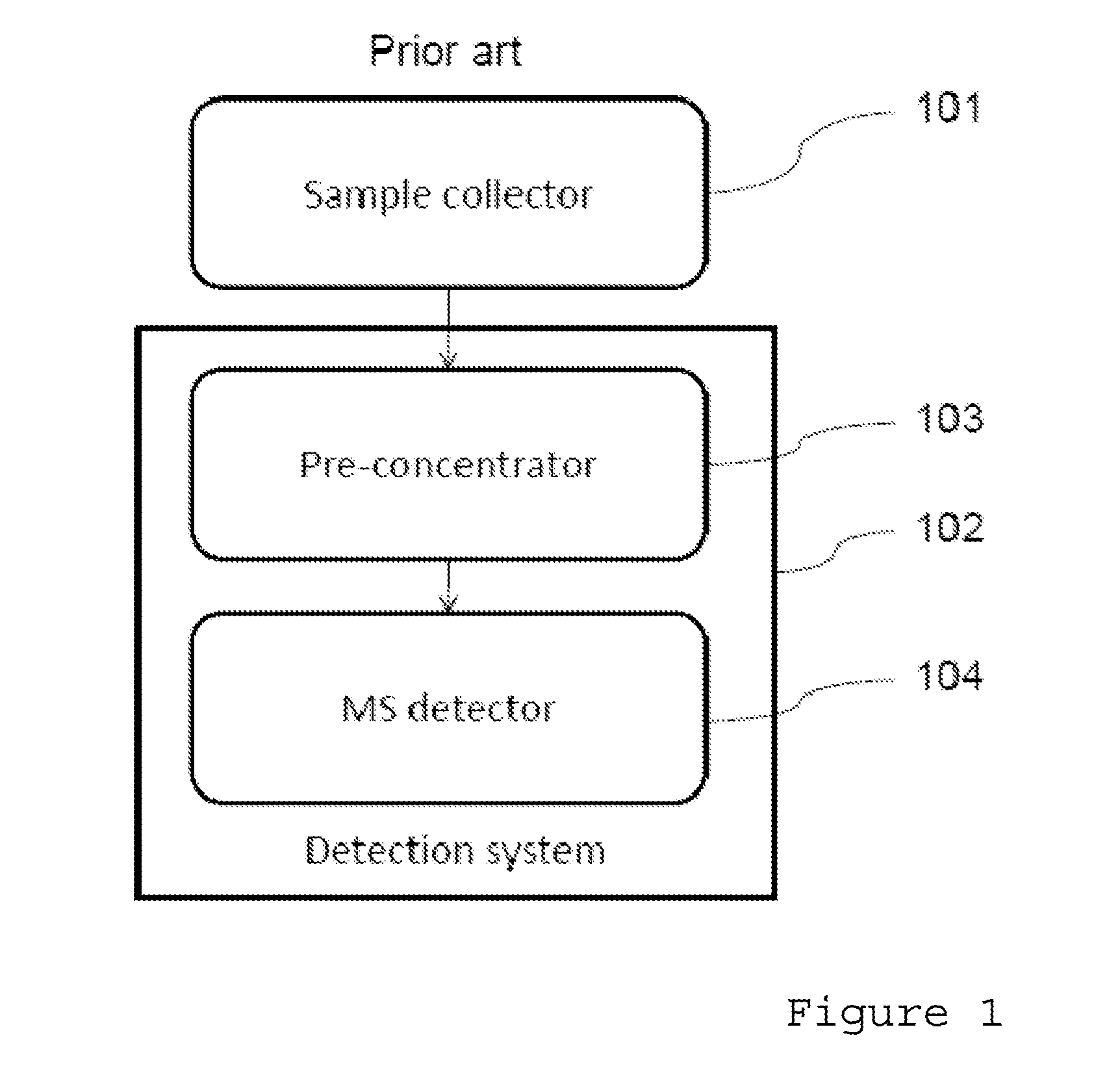
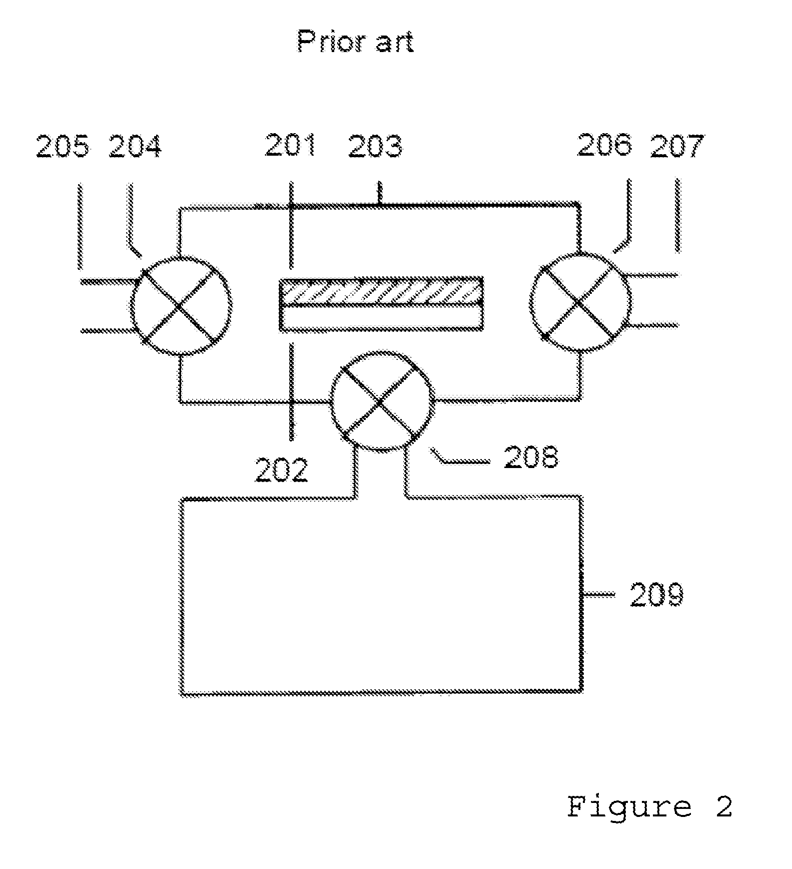
However, the hand-portable sample collection devices of the type disclosed have the disadvantage of being relatively expensive, bulky units which typically include pumps, sorbent tubes, valves and flow meters.
The size and cost of these units limits their deployability—a sample collection device with a weight of four pounds is excessive and cannot be given to every soldier unless it is at the expense of other equipment.
More importantly, for the sample collector disclosed in WO2006062906 and similar single stage pre-concentrators, there are difficulties in efficiently transferring the collected sample to the preferred analytical system, a gas chromatography mass spectrometer (GC-MS) without diluting the sample through dead volumes, or loosing sample to ‘cold spots’ or chemically active surfaces.
These difficulties may increase the technical complexity of the analysis, increase the duration of the analysis, and lead to loss of potentially valuable sample.
In particular, the flow rate, and therefore the response time, of the GC may be limited by the pumping speed of the pumps of the MS vacuum system.
However, a major drawback of this technique is that the sample must be presented on a surface, in a liquid or solid phase, to the DESI spray.
Vapours cannot be directly analysed by DESI in this fashion.
Another drawback is that a loss of ions due to scattering between the sample and the inlet to the mass detector leads to a drop in efficiency.
A further drawback is that in the absence of chemical separation the DESI-MS scheme, in the presence of a complex chemical matrix, suffers from chemical interference and a poor signal to noise ratio.

Method used


Image

  • Sample Collection and Detection System
  • Sample Collection and Detection System
  • Sample Collection and Detection System

Examples


Embodiment Construction

[0032]A detailed description of preferred exemplary embodiments of the invention is provided with reference to FIGS. 3 to 10. It will be understood that these embodiments are provided to assist in an understanding of the teaching of the invention and is not intended to limit the scope of the invention to the specifics of the features described herein. Furthermore it will be understood that where elements or features are described with reference to any one specific embodiment or Figure that these could be interchanged with or replaced by those of other embodiments or Figures without departing from the scope of the claimed invention.

[0033]It will be appreciated that most samples collected in a ‘real-world’ environment are ‘messy’ e.g. waste water, fuel oil spillage. Samples collected in during building or vehicle searches are generally complex chemical matrices comprising hundreds or even thousands of chemical components. The presence of pollutants, fuel oils and other chemical interf...


PUM


Abstract

A sample collection and detection system is described. The detection system provides a sample chamber fluidly coupled to a secondary ionisation source to allow the introduction of vapour generated from the sample into an ion path generated from the secondary ionisation source. The secondary ionisation source is a secondary electrospray ionisation (SESI) source, and is usefully employed in dust analysis.

Description

CROSS-REFERENCE TO RELATED APPLICATIONS[0001]This application claims the benefit of Great Britain Patent Application No. GB0920939.6 filed on Nov. 30, 2009.TECHNICAL FIELD OF THE INVENTION[0002]The present invention relates to on-site chemical analysis of samples and in particular to a detection system for the rapid on-site chemical analysis and to detachable sample collectors for use with detection systems. In particular, the invention provides for a detachable sample collector that operatively mates with a mass spectrometer system and can transfer a collected species of interest to a soft ionization source and a mass spectrometer detector. The invention may also incorporate other stages between the detachable sample collector and the soft ionization source that may allow pre-concentration or chromatography of the species of interest and may also incorporate the functions of an injection volume to an analytical instrument.BACKGROUND OF THE INVENTION[0003]Portable chemical detector ...

Claims


Application Information

Patent Timeline
IPC IPC(8): H01J49/00
CPCG01N30/08G01N30/72H01J49/165H01J49/145H01J49/0459H01J49/0022
Inventor FINLAY, ALAN
Owner MICROSAIC SYST
Learn More