Transceivers

a transceiver and receiver technology, applied in transmission systems, modulated carrier systems, transmission systems, etc., can solve the problems of reduced reliability, increased power dissipation, and significant redundancy, and achieve the effect of reducing the performance requirement of data converters and rf components, reducing power consumption, and small form factor

Active Publication Date: 2011-06-09
LIME MICROSYST
View PDF14 Cites 16 Cited by
  • Summary
  • Abstract
  • Description
  • Claims
  • Application Information

AI Technical Summary

Benefits of technology

[0006]In some cases, a transceiver which can conform to a multitude of standards and frequency bands and yet can be implemented with a small form factor, low power and cost effectively can be provided by utilizing the digital technology in such a way so as to ease off the performance requirement of the data converters and the RF components. In other words, rather than applying brute force in either using multiple RF transceivers or an all digital single transceiver, novel algorithms, circuit architectures and careful frequency planning can be used to achieve the lowest complexity and highest level of integration whilst satisfying spurious emission criteria of the applicable standards.

Problems solved by technology

Unfortunately, these approaches tend to introduce a significant amount of redundancy and reduced reliability, require more die area for each additional transceiver, and draw additional current leading to more power dissipation, large form factor and excessive bill of materials.
On this basis a fully integrated transceiver covering a heterogeneous set of mobile standards has been one of the major challenges facing the designers.
In addition, an external image filter is required at the IF for which integration is difficult to achieve due to the high specification and large filter component values.
The implementation, however, suffers from the well known problems caused by LO leakage and DC offset, limiting its application to certain modulation schemes and frequencies.
In this architecture, a bandpass filter is required for the channel selection which can be implemented in integrated form; however the poor image rejection due to the limited performance of the on chip components is one of the major drawbacks.
The low-IF architecture also utilizes an LO synthesizer with low phase noise performance requirements, posing yet another design challenge.

Method used


Image

  • Transceivers
  • Transceivers
  • Transceivers

Examples


Embodiment Construction

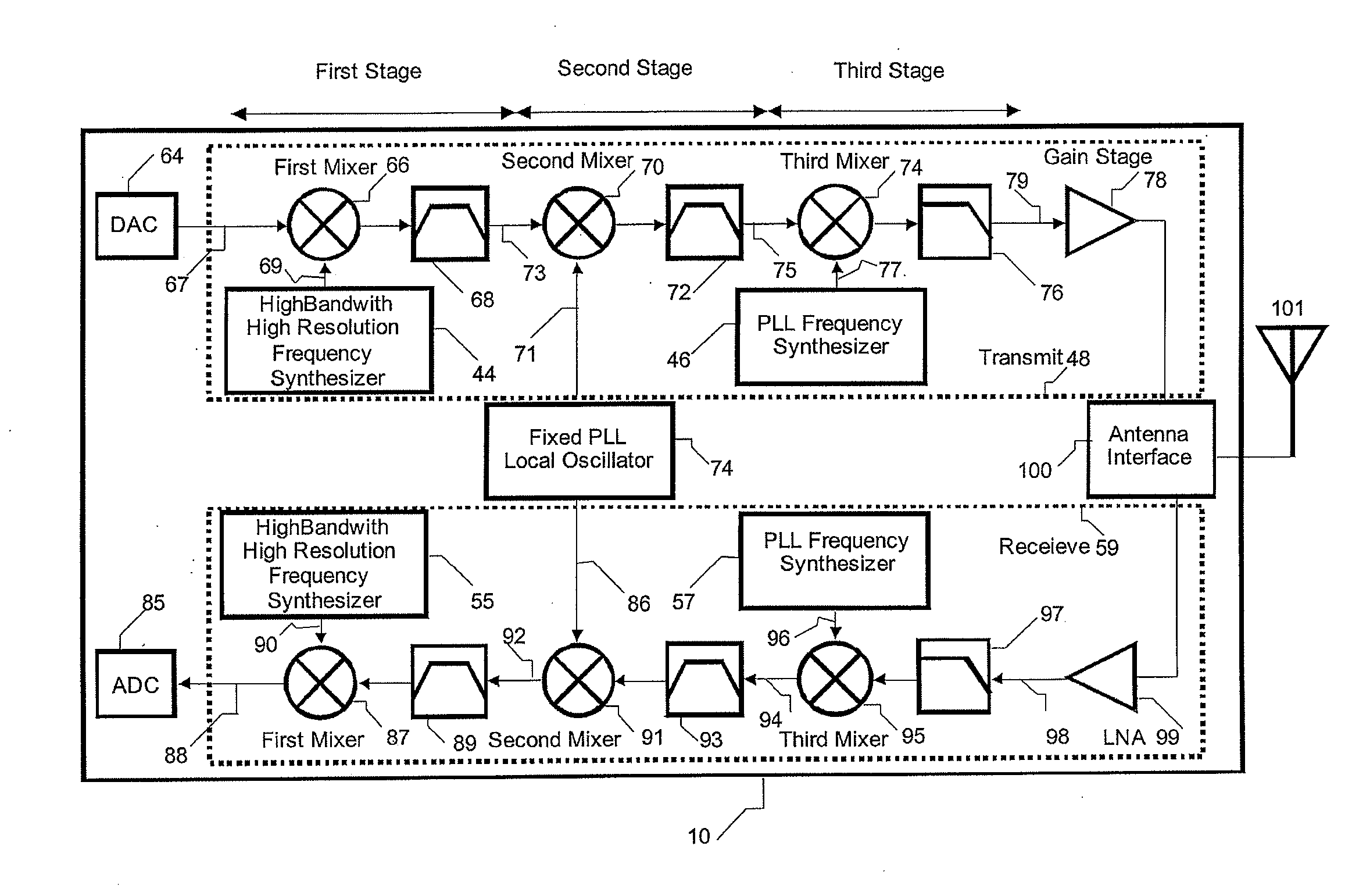
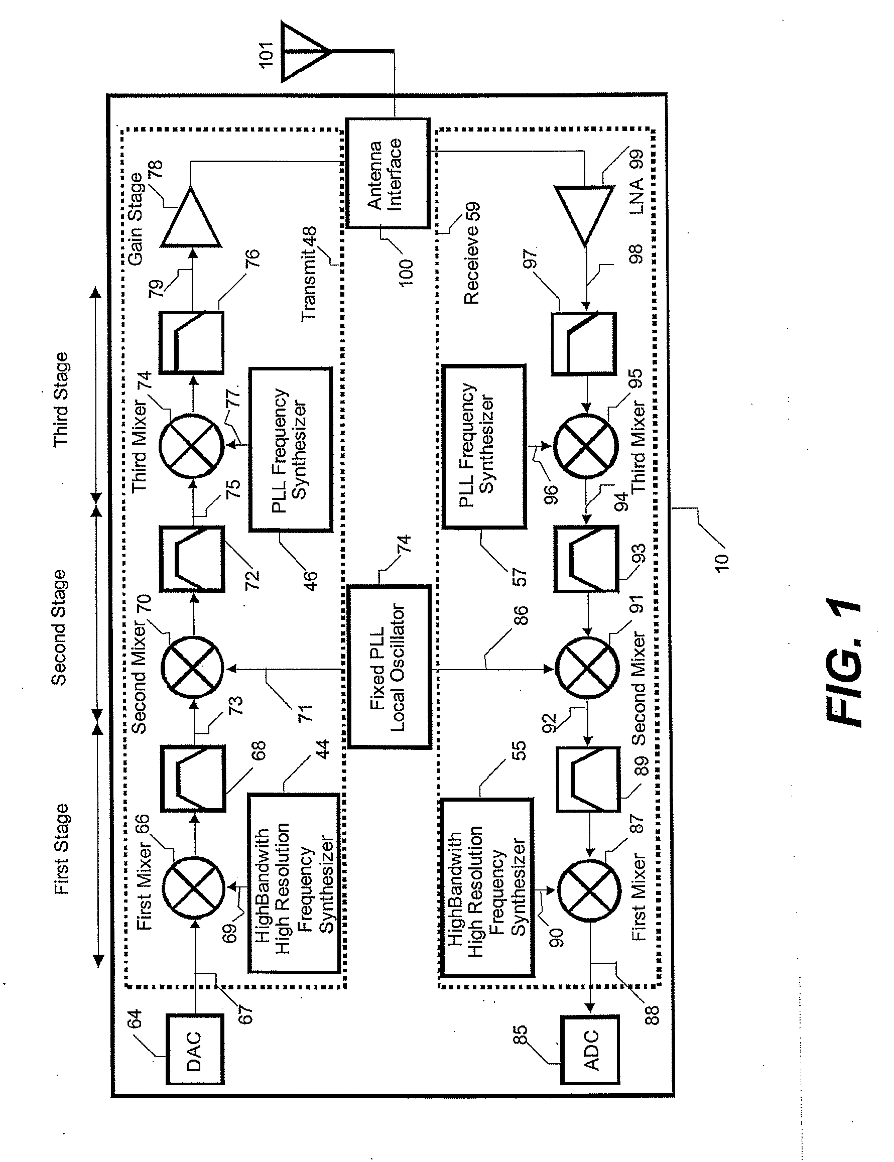
[0032]Embodiments of this invention in part include an architecture and frequency plan so as to achieve high level of integration for multi-band multi-standard transceivers. Additionally, embodiments of this invention in part relates to algorithms and circuit architectures so as to minimize hardware complexity in a preferred implementation. FIG. 1 illustrates a general block diagram of the transceiver circuitry 10 according to an embodiment of this invention. The transceiver consists of two separate paths: a Transmit path 48 that is responsible for frequency up conversion from DAC 64 output to an RF signal 79 driving a gain stage, and a Receive path 59 that is responsible for frequency down conversion from a pre-conditioned RF signal 98 at the output of LNA 99 to ADC 85 input. Each path consists of three stages namely first, second and third stages.

[0033]Considering the transmit circuitry 48, the first stage consists of the first mixer 66 coupled to a band pass filter 68 with the mi...


PUM


Abstract

An RF transceiver apparatus comprises transmitter circuitry arranged to convert signals from a baseband frequency to RF transmission frequencies and receiver circuitry arranged to convert signals from RF reception frequencies to the baseband frequency. The transmitter and receiver circuitry each comprise three mixers arranged to convert a signals between the baseband frequency, a first intermediate frequency; a second intermediate frequency that is higher than the transmission frequencies; and a second intermediate frequency to the transmission frequency.

Description

FIELD OF THE INVENTION[0001]This invention relates to wireless transmitters and receivers (transceivers). More particularly, the invention concerns broadband multi-standard transceivers using multistage transceiver architecture.BACKGROUND TO THE INVENTION[0002]The proliferation of mobile communication devices including mobile phones, personal digital assistants (PDAs) and laptops has resulted in significant efforts to provide efficient wireless transmission through adoption of new standards, hardware improvements and more sophisticated network management. As a result, there has been an ever increasing pressure to reduce cost, size and power consumption of such systems. This has driven designers to develop transceivers with higher levels of integration with much of the work focused on replacing the external components with integrated counterparts. This is not a trivial matter and often necessitates design of completely new transceiver architectures to achieve fewer off chip component...

Claims


Application Information

Patent Timeline
Patent Type & Authority Applications(United States)
IPC IPC(8): H04W88/02H04L27/00
CPCG06F1/0255H03M7/3026H03M7/3033H04B2001/0491H04B1/28H04B1/403H04B1/04H03B28/00H03D7/161
Inventor MILENKOVIC, SRDJANWEBSTER, DANNYBUSHEHRI, EBRAHIMKURYLO, RISARD
Owner LIME MICROSYST
Why Eureka
Try Eureka