Photobioreactor for carbon dioxide mitigation in wastewater treatment

a photobioreactor and wastewater treatment technology, applied in bioreactors/fermenters, biomass after-treatment, biochemical apparatus and processes, etc., can solve the problems of insufficient mixing, medium susceptible to airborne microorganisms and dust contamination, lack of temperature and light control, etc., to increase the usage efficiency of light energy by microalgae, the effect of large light specific area

Active Publication Date: 2011-06-30
TONGJI UNIV
View PDF4 Cites 38 Cited by
  • Summary
  • Abstract
  • Description
  • Claims
  • Application Information

AI Technical Summary

Benefits of technology

[0015]The invention is integrated with characteristics of present photobioreactors and traditional fermenters, the appropriate proportion of light area and dark area, the dispensing of different carbon sources and distribution of molecular oxygen are designed according to microalgae photoautotrophic-heterotrophic carbon sequestration photobioreactor. in terms of optimizing gas (CO2)-liquid mass transfe...

Problems solved by technology

As the open photobioreactor has disadvantages—such as lack of temperature and light control, inadequate mixing, medium susceptible to being contaminated by air-borne micro-organisms and dust.
So that there is instability in culture conditions, low photosynthetic efficiency and carbon sequestration efficiency, low overall productivity (the concentration of microalgae in general is 0.1-0.5 g/L or so); and narrow scope of application (only applicable to few microalgae species such as Spirulina, Chlorella, Dunaliella salina).
Most of the existing tubular photobioreactors have the following problems: ① There are difficulties in gas exchange addition of carbon and release of oxygen in the tube cannot be done in time.
② Serious algal cell damage is easily caused because of large shear stress when using mechanical pumps to circulate the algae fluid (Gudin & Chaumont, 1991).
Large-scale mixing is even more uneven and mass transfer efficiency is poor.
③ A plug flow state easily forms in the thin and long straight tube, and there are difficulties in forming a good mixing in the cross-section.
Due to shading of light by microalgae and limited light path length, microalgae in the reactor cannot receive photon adequately, and the light conversion efficiency of the reactor is low; ④ It is difficult to clean once there is attached-growth of the algae on the internal wall of reactor; ⑤ Investment and maintenance costs are high.
The structure of plate box type reactor is simple, but it also has some disadvantages, mainly: ① light supply and utilization efficiency.
When using the external natural light, most patents did not consider how to effectively enhance...

Method used


Image

  • Photobioreactor for carbon dioxide mitigation in wastewater treatment
  • Photobioreactor for carbon dioxide mitigation in wastewater treatment
  • Photobioreactor for carbon dioxide mitigation in wastewater treatment

Examples


example 1

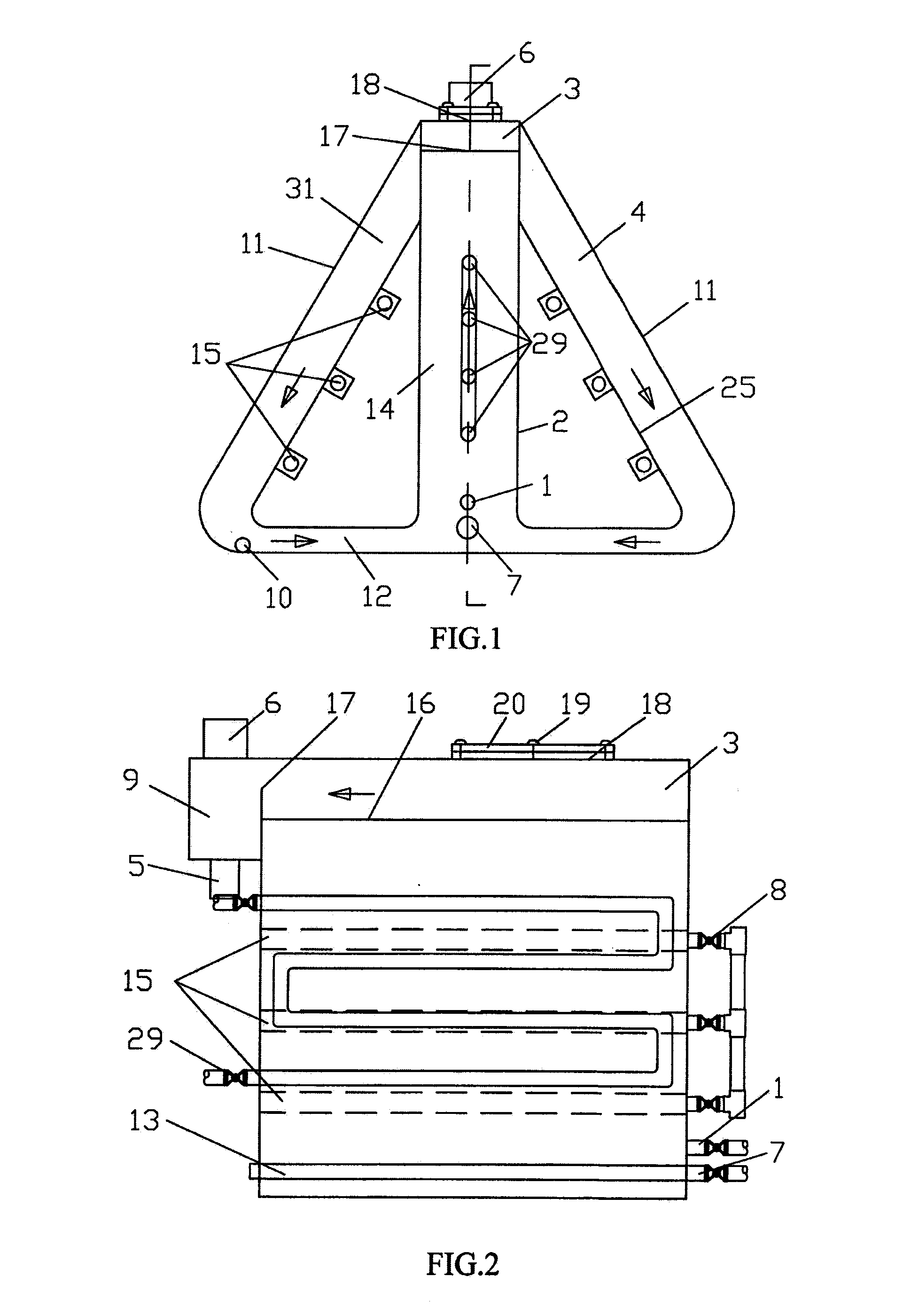
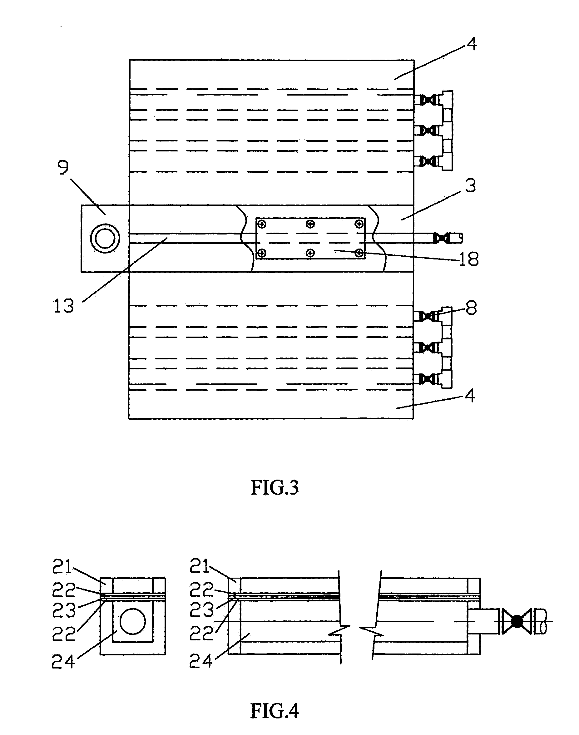
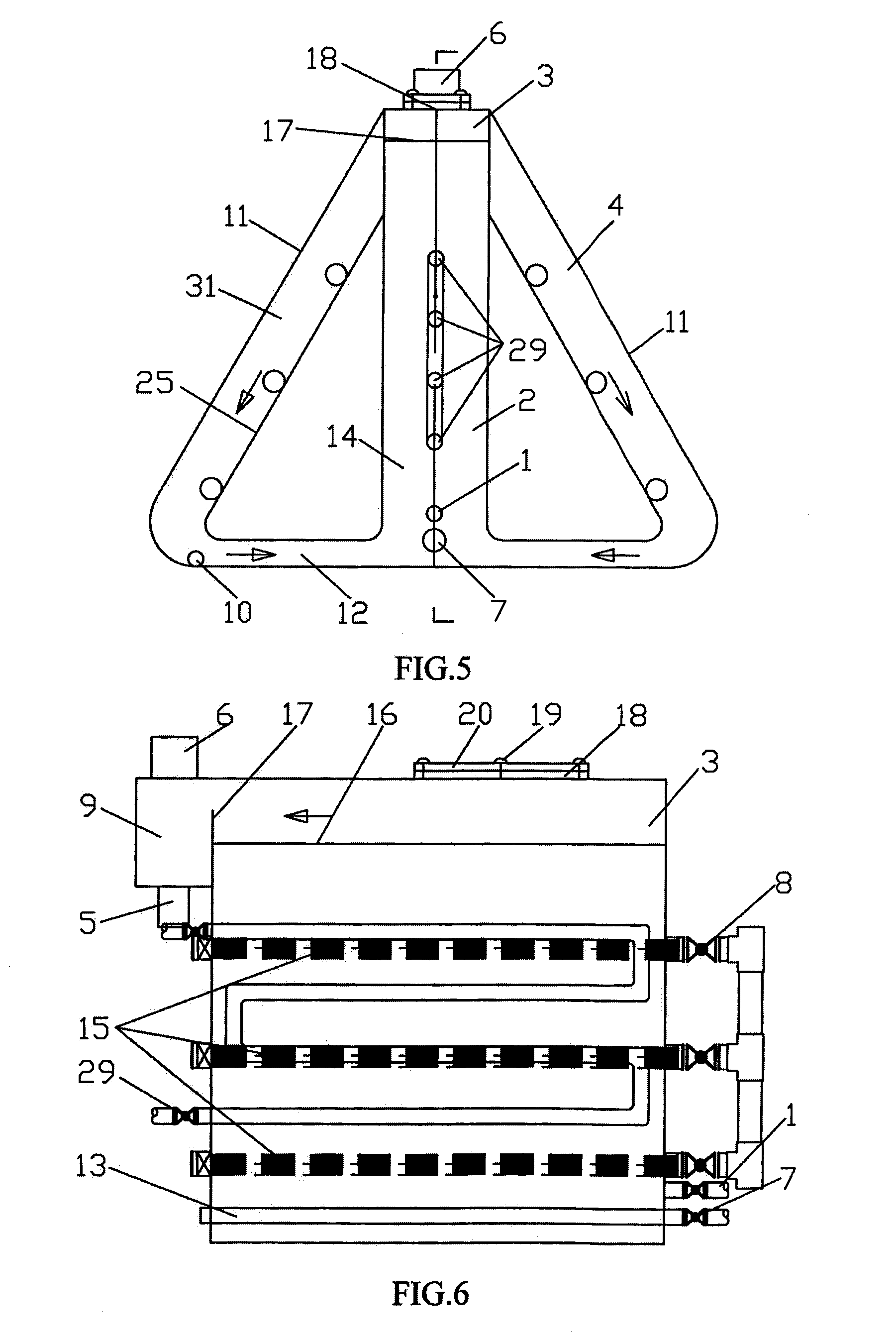
[0048]Operation Mode 1. Just as FIG. 1-3 show, the overall shape of the airlift circulation microalgae photoautotrophic-heterotrophic coupling photo-bioreactor for wastewater treatment carbon emission mitigation is a long ladder consisting of several trapezoid in line arrangement, including: feed pipe (1), microalgae heterotrophic zone (2), gas-liquid separation chamber (3), microalgae phototrophic zone (4), the bottom backflow zone (12) and liquid discharging zone (9). The arrows in the drawings of the reactor stand for the flow direction of the algal liquid.

[0049]Microalgae heterotrophic zone (2) in rectangular parallelepiped shape is the main reaction zone of microalgae heterotrophic growth utilizing the organic matter in the wastewater, which top connects with gas-liquid separation chamber (3) and which bottom connects with the bottom backflow zone (12). It includes feed pipe (1), air inlet pipe and flow control valve (7), air diffusion aerator (13), algal liquid lifting zone (1...


PUM


Abstract

An airlift circulation micro-algae photoautotrophic-heterotrophic coupling photobioreactor for wastewater treatment carbon emission mitigation includes feeding pipe, micro-algae heterotrophic zone, gas-liquid separation chamber, micro-algae phototrophic zone, bottom backflow zone, discharge pipe, and the liquid drained zone.

Description

FIELD OF THE INVENTION[0001]This invention belongs to the field of wastewater treatment technology, specifically relates to an airlift circulation microalgae photoautotrophic-heterotrophic coupling photobioreactor for wastewater treatment carbon emission mitigation.BACKGROUND OF THE INVENTION[0002]Atmospheric carbon dioxide (CO2) concentration being from pre-industrial 270 ppm to the current 380 ppm, CO2 emission mitigation has become the focus of global concern. The government has attached great importance to the issue; all walks of life are working hard to explore the new technologies of CO2 emission mitigation, especially in the wastewater treatment process.[0003]Microalgae and cyanobacteria (blue-green algae) can convert H2O and CO2 into organic compounds by photosynthesis using photon energy, and has the growth and reproduction capabilities by using mineral nutrients and some organic compounds which are absorbed from the environment. Therefore, it can be used for absorption of ...

Claims


Application Information

Patent Timeline
IPC IPC(8): C12M1/00
CPCC12M21/02C12M29/04C12M23/34C12M29/16C12M23/06C12M29/08C12M41/24
Inventor ZHANG, YALEIZHOU, XUEFEISU, HONGYANGCHEN, XIAOZHANG, CHUNMINLI, JINPENG
Owner TONGJI UNIV
Why Eureka
Try Eureka