[0006]In addition to the planar anode baskets and intermittently scraped cathode rods, the PEER design also allows for simple removal of the electrorefined uranium product by collection of the scraped cathode deposit in a basket that is periodically removed from the unit, emptied, and then replaced. Direct removal of the electrorefined product allows the PEER to be passing current, and thus refining the material nearly 100% of the time.
[0008]In the electrorefining of spent reactor fuel, the actinides, TRU's and active
metal fission products are oxidized at the anode and dissolve in the
molten salt electrolyte as
metal cations. Under normal operating conditions, only uranium is deposited on the cathode. However, if the cathode potential can be made sufficiently negative, uranium and TRUs will codeposit on the cathode. The key to obtaining a sufficiently negative cathode potential is a high
cathode current density that depletes uranium from the
molten salt electrolyte near the cathode surface. In a practical sense, for this to occur in a uranium electrorefiner in which the electrolyte is molten LiCl-KCl, the anode area must greatly exceed the cathode area. The necessary difference in anode vs. cathode areas is needed because the
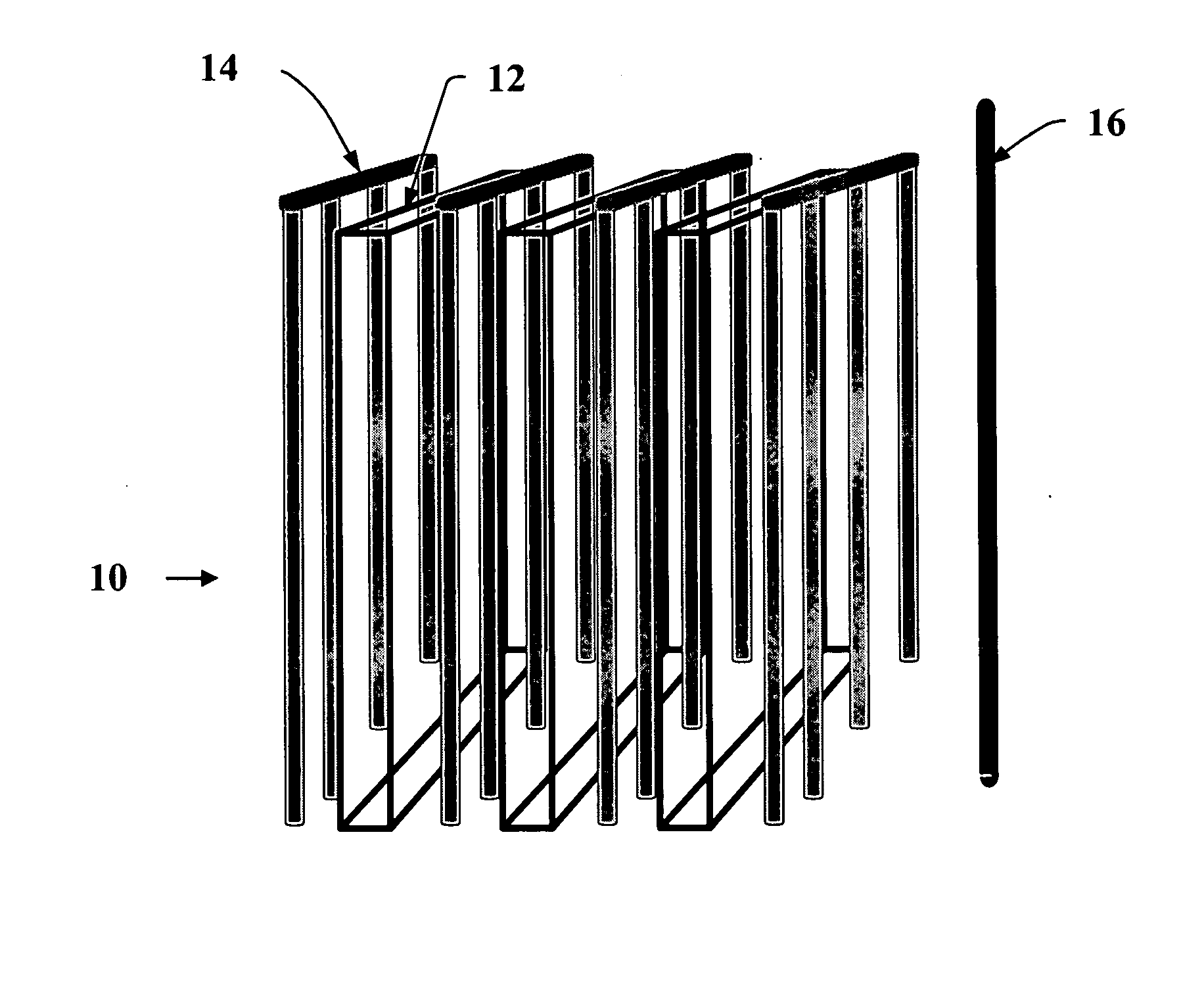
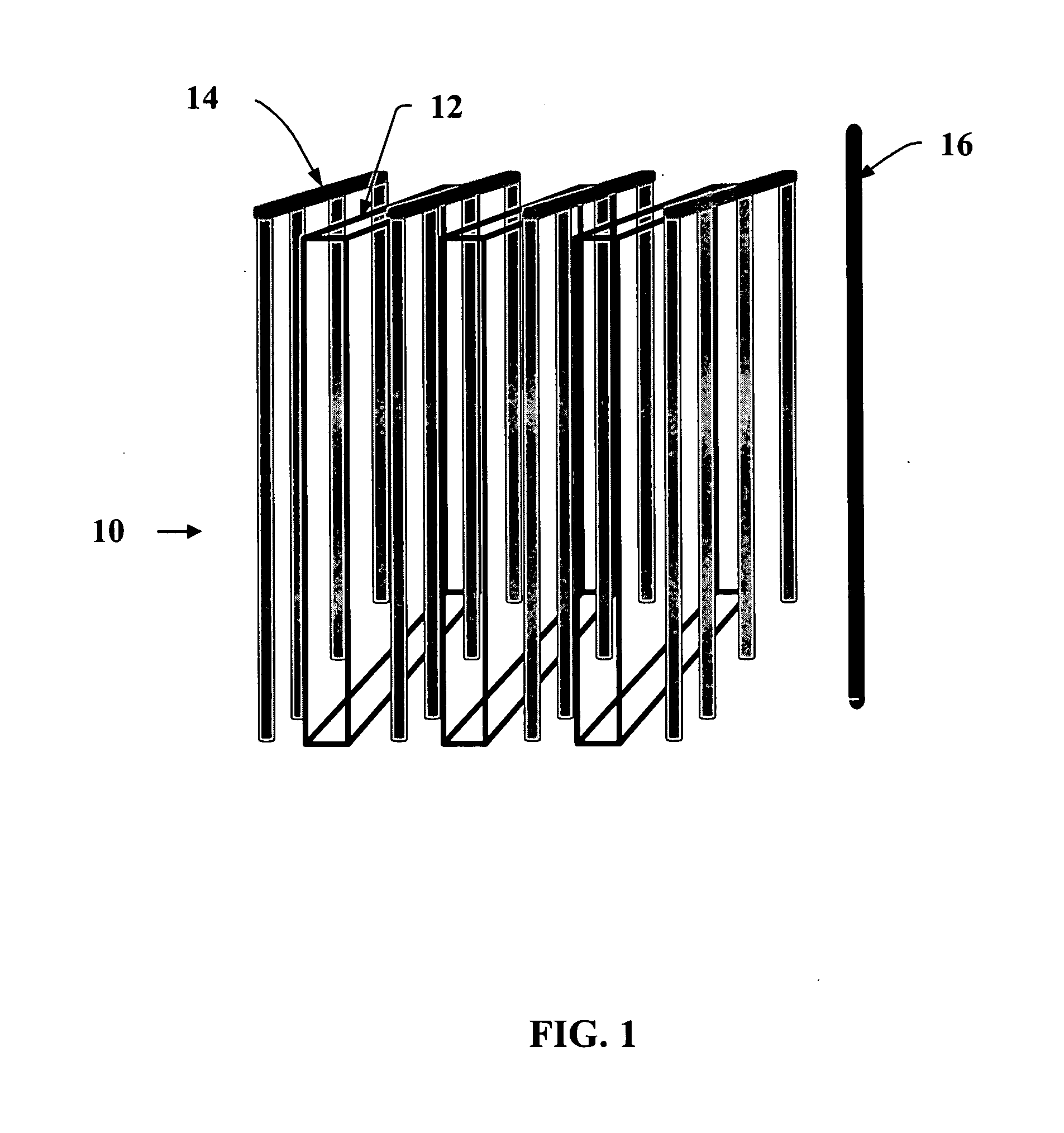
limiting current density for uranium oxidation at the anode is surprisingly low at potentials that will not oxidize the structural steel in the anode basket. Achieving a sufficiently high anode-to-cathode surface area makes it possible to codeposit U and TRUs on a solid cathode. The PEER design uses multiple planar anode baskets with interleaved linear cathode arrays between the baskets. By disconnecting the linear cathode arrays and adding an additional cathode rod to the side of the anode baskets necessary anode-to-cathode
area ratio can be achieved. The U / TRU deposit can be intermittently scraped off the cathode and removed in the same manner as the
uranium deposit is scraped off and removed as described previously.
[0009]The methods of the present invention have several advantages over existing processes that employ a liquid
cadmium or
bismuth cathode. First, this invention eliminates the use of
cadmium and the
engineering challenges of operating a
liquid metal cathode. Second, this invention achieves a greater degree of separation between TRUs and rare earths than can ever be achieved with a liquid
cadmium cathode. This invention also has a strong nuclear proliferation-resistance aspect, in that as long as the material used in the anode basket is spent fuel that contains a significant fraction of uranium, it is impossible to obtain a pure
plutonium (or uranium-free TRU) product at the cathode, because uranium will always be present in the
system and codeposit with the TRUs.
[0010]Accordingly, the present invention provides a method of simultaneously removing uranium and transuranics from metallic nuclear fuel containing both uranium and transuranics in an electrorefiner having a solid cathode and an anode basket containing the metallic nuclear fuel and a molten
halide electrolyte. The process comprises (a) establishing a
potential difference between the anode basket and solid cathode, thereby creating a
diffusion layer of uranium and transuranic ions at the solid cathode, a first current density at the anode basket, and a second current density at the solid cathode; (b) establishing a ratio of anode basket area to solid cathode area dependent on the total concentration of uranium and transuranics in the molten
halide electrolyte and the effective thickness of the
diffusion layer at the solid cathode, such that the established first and second current densities result in both codeposition of uranium and transuranics on the solid cathode and oxidation of the metallic nuclear fuel in the anode basket; (c) maintaining the first and second current densities at levels sufficient to codeposit uranium and transuranics on the solid cathode; (d) removing deposited material from the solid cathode; and (e) controlling the first current density at the anode basket to prevent substantial oxidation of the anode basket during operation of the electrorefiner.
[0011]The present invention also provides a method of simultaneously removing uranium and transuranics from metallic nuclear fuel containing both uranium and transuranics in an electrorefiner having a solid cathode and an anode basket containing the metallic nuclear fuel and a molten halide electrolyte. In this aspect, the process comprises (a) establishing a
potential difference between the anode basket and solid cathode, thereby creating a
diffusion layer of uranium and transuranic ions at the solid cathode, a first current density at the anode basket, and a second current density at the solid cathode; (b) establishing a ratio of anode basket area to solid cathode area dependent on the total concentration of uranium and transuranics in the molten halide electrolyte and the effective thickness of the
diffusion layer at the solid cathode, such that the first current density is maintained in the range of about 70 mA / cm2 to about 100 mA / cm2, and the second current density at the solid cathode is maintained in the range of greater than about 200 to about 1400 mA / cm2, resulting in both codeposition of uranium and transuranics on the solid cathode and oxidation of the metallic nuclear fuel in the anode basket; (c) maintaining the first and second current densities at levels to codeposit uranium and transuranics on the solid cathode; (d) removing deposited material from the solid cathode; and (e) controlling the first current density at the anode basket to prevent substantial oxidation of the anode basket during operation of the electrorefiner.
[0012]In addition, the present invention provides a method of simultaneously removing uranium and transuranics from metallic nuclear fuel containing both uranium and transuranics in an electrorefiner having a solid cathode and a plurality of electrically connected anode baskets containing the metallic nuclear fuel and a molten halide electrolyte, the anode baskets including opposed planar meshes establishing contact between the metallic nuclear fuel and the molten electrolyte. In this aspect, the process comprises (a) establishing a potential difference between the anode basket and solid cathode, thereby creating a diffusion layer of uranium and transuranic ions at the solid cathode, a first current density at the anode basket, and a second current density at the solid cathode; (b) establishing a ratio of anode basket area to solid cathode area dependent on the total concentration of uranium and transuranics in the molten halide electrolyte and the effective thickness of the diffusion layer at the solid cathode such that the established first and second current densities result in both codeposition of uranium and transuranics on the solid cathode and oxidation of the metallic nuclear fuel in the anode basket; (c) maintaining the first and second current densities at levels to codeposit uranium and transuranics on the solid cathode; (d) removing deposited material from the solid cathode; and (e) controlling the first current density at the anode basket to prevent substantial oxidation of the anode basket during operation of the electrorefiner.

