
Method for manufacturing separators, separators manufactured by the method and electrochemical devices including the separators

a technology of electrochemical devices and separators, which is applied in the direction of cell components, cell component details, electrochemical generators, etc., can solve the problems of disadvantageous complex fabrication, thermal runaway, and safety problems of lithium ion batteries, and achieve excellent electrochemical device performance, reduce damage to the surface of porous substrates, and improve productivity

Active Publication Date: 2011-08-11
LG ENERGY SOLUTION LTD +1
View PDF2 Cites 19 Cited by
  • Summary
  • Abstract
  • Description
  • Claims
  • Application Information

AI Technical Summary

Benefits of technology

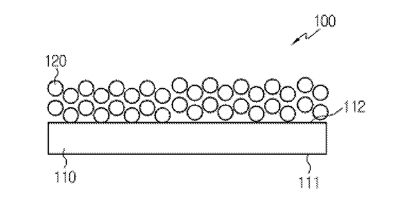
[0009]An aspect of the present invention is to provide a method for manufacturing separators in which a porous substrate is coated with an organic-inorganic binder slurry to form an organic-inorganic composite coating layer, resulting in enhanced productivity.
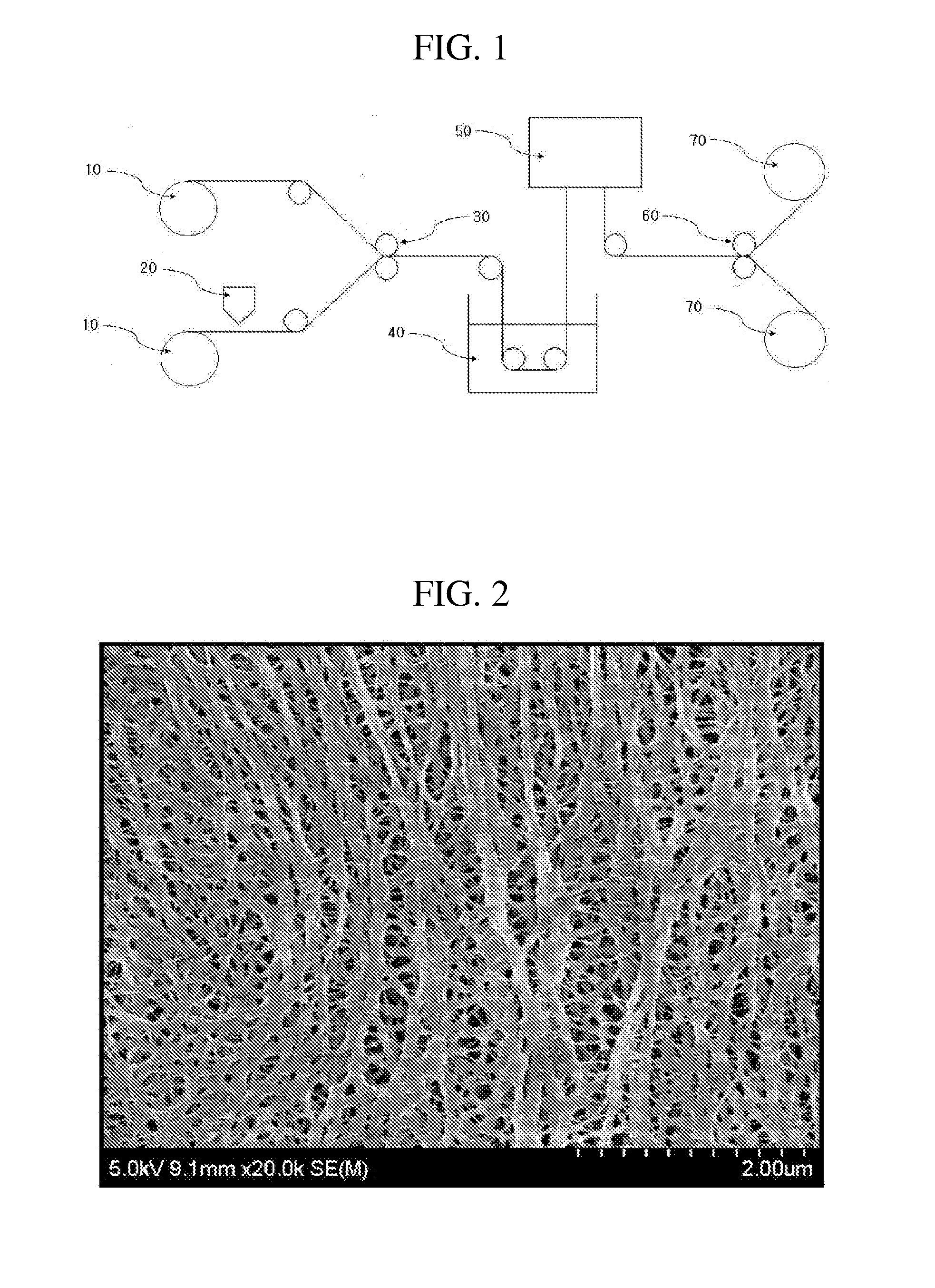
[0022]According to the method of the present invention, two separators can be simultaneously manufactured with enhanced productivity. In addition, corona discharge can reduce damage to the surfaces of the porous substrates during lamination while maintaining the porosities of the porous substrates, thus ensuring excellent performance of electrochemical devices using the separators.

Problems solved by technology

However, such lithium ion batteries suffer from safety problems, such as fire or explosion, encountered with the use of organic electrolytes and are disadvantageously complicated to fabricate.
Overheating of an electrochemical device may cause thermal runaway or puncture of a separator may pose an increased risk of explosion.
This thermal shrinkage behavior may cause short-circuiting between a cathode and an anode.
The formation of the two coating layers on the single substrate by dip coating is economically undesirable.

Method used


Image

  • Method for manufacturing separators, separators manufactured by the method and electrochemical devices including the separators
  • Method for manufacturing separators, separators manufactured by the method and electrochemical devices including the separators
  • Method for manufacturing separators, separators manufactured by the method and electrochemical devices including the separators

Examples


example 1

Manufacture of Separators Including Porous Substrate Treated by Corona Discharge

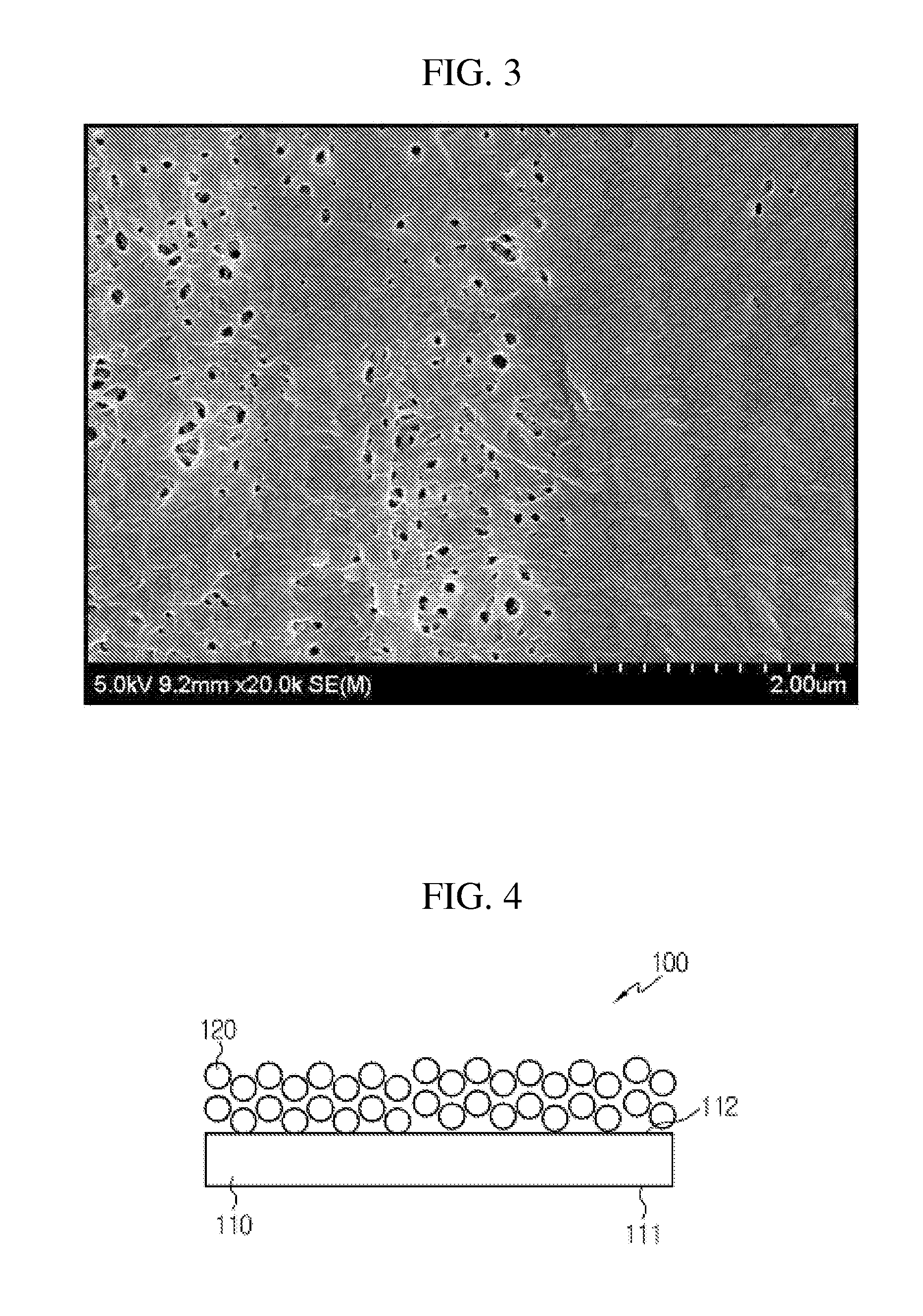
[0064]A mixture of polyvinylidene fluoride-co-hexafluoropropylene (PVdF-HEP) and cyanoethylpullulan (10:1.75 (w / w)) was dissolved in acetone at 50° C. for about 12 hr to prepare a polymer solution. Barium titanate (BaTiO3) powder as an inorganic material was added to the polymer solution such that the weight ratio of the polymer mixture to the inorganic material was 9:1. The inorganic particles were crushed and dispersed in the mixture by ball milling to prepare a slurry. The inorganic particles of the slurry were an average particle diameter of 600 nm.

[0065]One surface of 12 μm thick polyethylene porous membranes (porosity: 45%, Gurley value: 230 sec / 100 mL) was treated by corona discharge at a watt density of 80 Wmin / m2. The porosity and Gurley value of the polyethylene porous membranes after corona discharge were maintained constant (45% and 232.5 sec / 100 mL, respectively), which were substantially th...


PUM

PropertyMeasurementUnit
porosityaaaaaaaaaa
pore sizeaaaaaaaaaa
thicknessaaaaaaaaaa

Abstract

A method for manufacturing separators includes (S1) treating at least one of the laminating surfaces of two porous substrates by corona discharge and laminating the porous substrates, (S2) preparing a slurry containing inorganic particles dispersed therein and a solution of a binder polymer in a solvent, and coating the slurry on both surfaces of the laminate of the porous substrates, and (S3) delaminating the coated laminate of the porous substrates. According to the method, two separators can be simultaneously manufactured with enhanced productivity. In addition, corona discharge can reduce damage to the surfaces of the porous substrates during lamination while maintaining the porosities of the porous substrates. Therefore, excellent performance of electrochemical devices using the separators can be ensured.

Description

CROSS-REFERENCE TO RELATED APPLICATION[0001]This application is a continuation of International Application No. PCT / KR2010 / 008402 filed on Nov. 25, 2010, which claims priority to Korean Patent Application No. 10-2009-0115568 filed in the Republic of Korea on Nov. 27, 2009, and Korean Patent Application No. 10-2010-0117922 filed in the Republic of Korea on Nov. 25, 2010, the entire contents of which are incorporated herein by reference.FIELD OF THE INVENTION[0002]The present invention relates to a method for manufacturing separators for electrochemical devices such as lithium secondary batteries, separators manufactured by the method, and electrochemical devices including the separators.BACKGROUND OF THE INVENTION[0003]Recently, there has been increasing interest in energy storage technologies. As the application fields of energy storage technologies have been extended to mobile phones, camcorders, notebook computers and even electric cars, efforts have increasingly been made towards...

Claims


Application Information

Patent Timeline
Patent Type & Authority Applications(United States)
IPC IPC(8): H01M2/14H01M2/16B32B38/10H01M50/403H01M50/457H01M50/491
CPCH01M2/14H01M2/145H01M2/166H01M10/4235H01M2/18H01M10/052H01M2/1686B32B27/00B32B2597/00B32B27/06B32B2307/50B32B2457/00Y02E60/10H01M50/446H01M50/403H01M50/457H01M50/491
Inventor LEE, JOO-SUNGKIM, JONG-HUN
Owner LG ENERGY SOLUTION LTD
Learn More