
Fouling Resistant Membranes Formed with Polyacrylonitrile Graft Copolymers

a polyacrylonitrile and copolymer technology, applied in water/sewage treatment, filtration separation, osmosis/dialysis, etc., can solve the problems of reducing the lifetime of the membrane, affecting the filtration effect, and increasing the energy requirements

Active Publication Date: 2011-08-18
THE UNITED STATES OF AMERICA AS REPRESENTED BY THE SECRETARY OF THE NAVY +1
View PDF34 Cites 12 Cited by
  • Summary
  • Abstract
  • Description
  • Claims
  • Application Information

AI Technical Summary

Benefits of technology

[0009]This invention is generally directed to polyacrylonitrile— (PAN—) based amphiphilic graft copolymers, which can be used, for example, in the production of membranes for liquid filtration. The sub...

Problems solved by technology

Membrane fouling is one of the more important problems in the membrane industry.
Flux decline typically leads to higher energy requirements, and frequent cleaning is usually required to remedy this.
This is only a temporary solution, and fouling typically ultimately reduces the lifetime of the membrane.
This method, however, only functionalizes the top surface of the membrane, so the fouling of internal pores is not prevented.
A significant drawback of these surface modification methods is the use of high-energy gamma radiation or plasmas to initiate graft polymerization.
These approaches may significantly increase membrane fabrication cost and are poorly controlled.
Undesirable side reactions include polymerization of ungrafted chains, which are susceptible to removal from the surface during use.
Such surface graft-polymerized layers can also block pores and deteriorate flux.
These methods all include several extra processing steps for the activation of reactive sites and coupling, and therefore can be relatively expensive.
Nevertheless, the ultrafiltration membranes produced still did not resist fouling completely and some irreversible flux loss was observed in studies using protein-containing feed solutions.

Method used


Image

  • Fouling Resistant Membranes Formed with Polyacrylonitrile Graft Copolymers
  • Fouling Resistant Membranes Formed with Polyacrylonitrile Graft Copolymers
  • Fouling Resistant Membranes Formed with Polyacrylonitrile Graft Copolymers

Examples


example 1

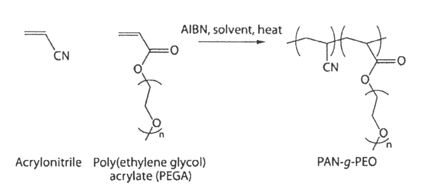
Synthesis of Polyacrylonitrile-graft-poly(ethylene glycol) (PAN-g-PEO) using Toluene as a Solvent

[0058]In this example, a graft copolymer with a PAN backbone and PEO side-chains, used in the preparation of certain membranes of the invention, was synthesized as follows. Acrylonitrile (Aldrich) and poly(ethylene glycol) methyl ether acrylate (PEGA) (454 g / mol, Aldrich) were passed through a column of basic activated alumina (VWR) to remove the inhibitor. Acrylonitrile (10 g, 188 mmol), PEGA (10 g, 22 mmol) and azobisisobutyronitrile (AIBN, 0.01 g, Aldrich) were dissolved in toluene (50 ml) in a round bottom flask. The flask was sealed. Nitrogen was bubbled through the reaction mixture with stirring for 20 minutes. The flask was then kept at 90° C. with stirring for 24 hours. The reaction mixture, which was observed to contain precipitated polymer, was then precipitated in hexane, and purified by stirring two fresh portions of hexane for several hours, followed by drying in the vacuum ...

example 3

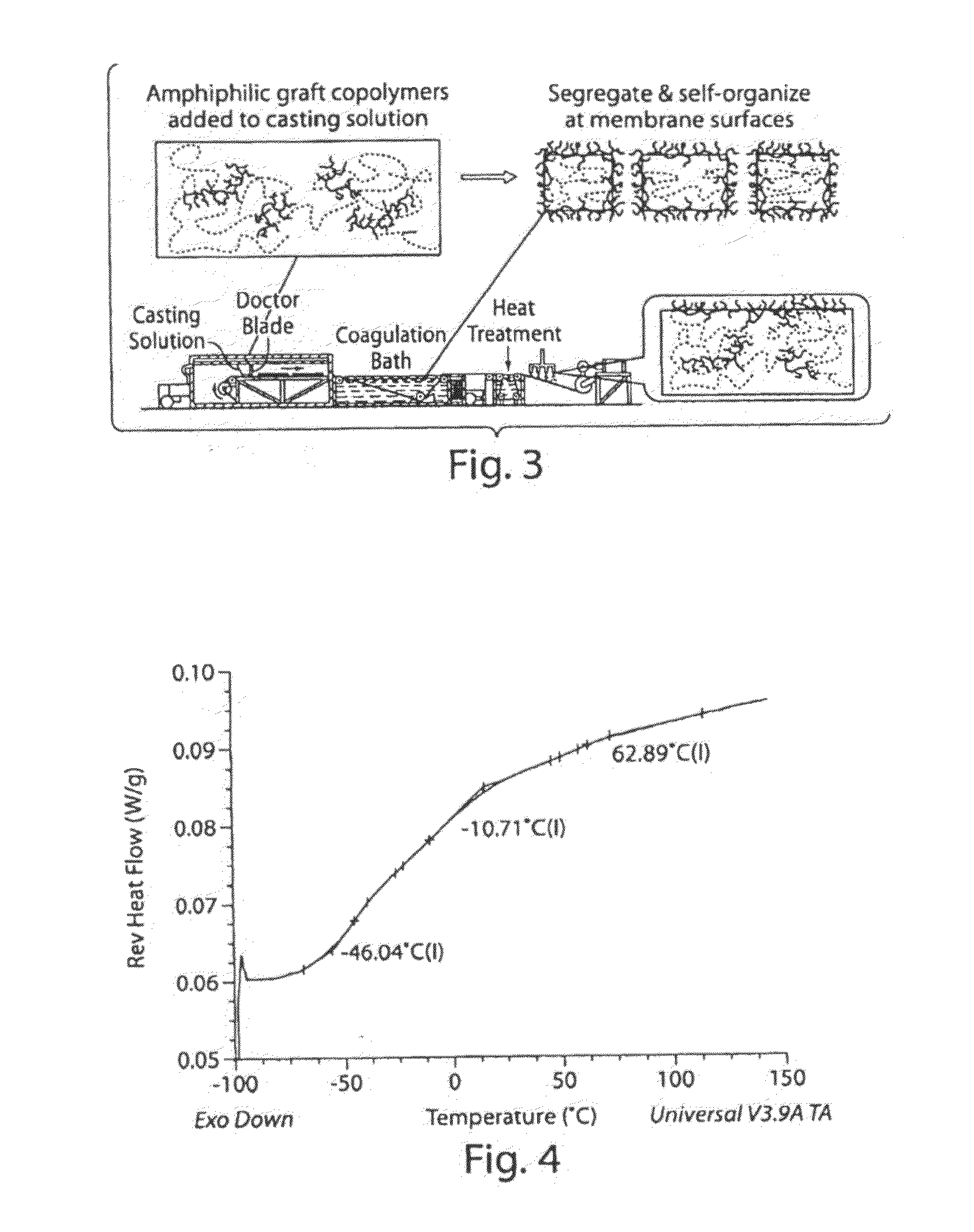
Microphase Separation Characteristics of PAN-g-PEO Samples with Different Casting Conditions

[0061]To observe the microphase separation characteristics of PAN-g-PEO, three different sets of samples were prepared for differential scanning calorimetry (DSC) testing in this example. DSC was done using a TA Instruments Q100 in modulated DSC (MDSC) mode so the kinetic effects could be removed from the obtained data and glass transitions could be observed more clearly through isolation of the reversible heat flow.

[0062]The first set of samples was aimed at simulating the conditions for membranes cast in isopropanol. For that, a glass microscope slide was covered with a thin layer of 20 wt % solution of PAN-g-PEO in DMF, so that approximately 0.3 ml of solution was spread over an area of 1.5 cm by 3 cm. The slide was then immersed in isopropanol for 30 minutes, followed by immersion in water for 10 minutes. The recovered transparent film detached from the glass and was dried in a vacuum ove...

example 4

Preparation of Thin Film Composite Nanofiltration Membranes from PAN-g-PEO

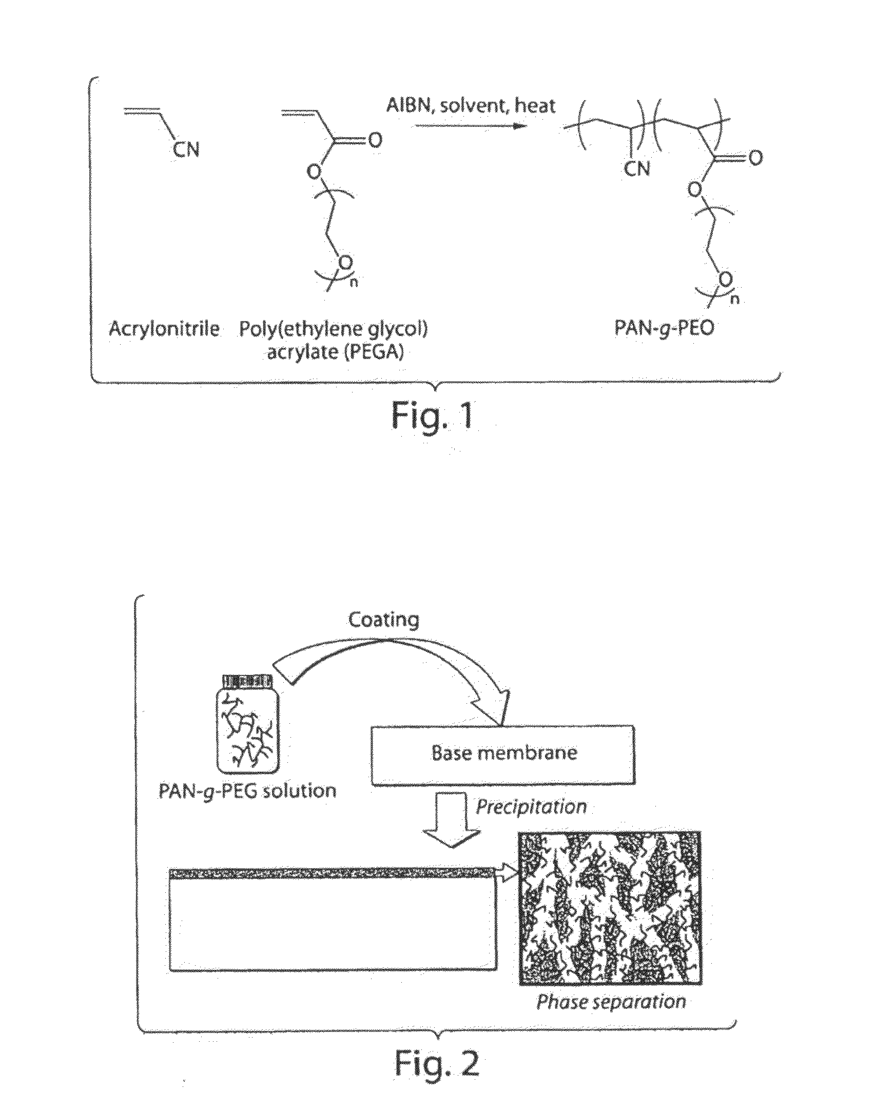
[0066]In this example, a nanofiltration membrane was prepared using the graft copolymer described in Example 1. The polymer (2 g) was dissolved in N,N-dimethylformamide (DMF, VWR, 8 ml) at approximately 50° C. The polymer solution was passed through a 1 micrometer syringe filter (Whatman) and degassed in a vacuum oven for at least 2 hours. A PAN400 ultrafiltration membrane, purchased from Sepro Inc. (Oceanside, Calif.), was used as the base membrane. The membranes were coated using a control coater (Testing Machines Inc., Ronkonkoma, N.Y.). The PAN400 base membrane was fixed onto the coater, and the coating bar (number 4, nominal film thickness 40 micrometers) inserted. The coating solution was poured onto the base membrane to form a thin line about 0.5 cm from the coating bar, and the coater was used to move the bar at a constant reproducible speed (speed level 4 on the instrument). After waiting for 5 minute...


PUM

PropertyMeasurementUnit
Fractionaaaaaaaaaa
Timeaaaaaaaaaa
Pore sizeaaaaaaaaaa

Abstract

The present application is generally directed towards polyacrylonitrile— (PAN—) based, amphophilic graft copolymers, for example, for the production of membranes for liquid filtration. In one aspect, the present invention provides systems and methods for preparing high flux, fouling resistant nanofiltration membranes whose pore size can be readily tuned. In some cases, microphase separation of a graft copolymer comprising a backbone comprising polyacrylonitrile (PAN) and hydrophilic side-chains is used. In some cases, nanochannels of tunable width are formed, which may give the membrane permselective properties and / or anti-fouling character. In some cases, a copoylmer may be used as an additive in the immersion precipitation casting of ultrafiltration or microfiltration membranes. In certain instances, the additive can segregate to the membrane exterior and / or pore surfaces, e.g., due to favorable interactions between the hydrophilic side chains and the surrounding environment, which may create a surface that resists fouling, e.g., by biological molecules.

Description

FIELD OF THE INVENTION[0001]This invention is generally directed to polyacrylonitrile— (PAN—) based amphiphilic graft copolymers, which can be used in the production of membranes for liquid filtration. In one aspect, this invention is directed to the preparation of nanofiltration (NF) membranes whose selective layer comprises microphase-separated PAN-based, amphiphilic graft copolymers, which display high flux, fouling resistance, and / or molecular fractionation (separation-of two or more species from solution) capability, e.g., at the sub-nanometer length scale. In another aspect, the invention is directed to the incorporation of PAN-based amphiphilic graft copolymers as an additive in the casting of ultrafiltration (UF) and / or microfiltration (MF) membranes, which may impart the membranes with resistance to irreversible fouling.BACKGROUND OF THE INVENTION[0002]A membrane is a discrete, thin interface that moderates the permeation of chemical species in contact with it. Water filtra...

Claims


Application Information

Patent Timeline
IPC IPC(8): B01D71/42B01D71/82B01D71/78
CPCB01D61/145B01D61/147B01D67/0093B01D69/02B01D71/42B01D2323/38B01D2323/02B01D2325/20B01D2325/36B01D65/08B01D2321/16B01D71/78B01D67/00931B01D71/421B01D71/82
Inventor MAYES, ANNE M.ASATEKIN ALEXIOU, AYSE
Owner THE UNITED STATES OF AMERICA AS REPRESENTED BY THE SECRETARY OF THE NAVY
Learn More