Method and apparatus for remotely performing hematologic analysis utilizing a transmitted image of a centrifuged analysis tube

a centrifuged and transmitted image technology, applied in the field of methods and apparatus for remotely performing hematologic analysis utilizing a transmitted image of a centrifuged analysis tube, can solve the problems of inaccurate data based on that band width, achieve the effect of avoiding cost, increasing the level of care available to the patient from the healthcare provider, and performing in a very short period of tim

Active Publication Date: 2011-08-18
QBC DIAGNOSTICS LLC +1
View PDF16 Cites 60 Cited by
  • Summary
  • Abstract
  • Description
  • Claims
  • Application Information

AI Technical Summary

Benefits of technology

[0009]A significant advantage associated with the present analysis system is that it provides application versatility. For example, the present analysis system allows sample testing that requires trained personnel to be performed in health care offices without trained personnel. The sample can be centrifuged and imaged in the healthcare office, and the image sent to a remotely located analysis provider office where a trained technician can perform the analysis. In this manner, a single analysis provider office can service a significant number of healthcare offices. As a result, the level and speed of care available to the patient from the healthcare provider is increased. In fact, the ability of the present analysis system to bi-directionally communicate one or both of the image and the analysis results means that the testing can be performed in a very short period of time; e.g., seconds to minutes. The present analysis system also avoids the cost of providing a trained technician at each of the healthcare offices. Another advantage of the present analysis system is its quality control capability. As will be described hereinafter, the present system makes it possible to periodically (or randomly) check the accuracy of a local analysis device though a centrally located analysis device, which central device may be operated by a trained technician. In addition, the quality control analyses can include review functions such as a determination of whether an automated analysis algorithm applied to the centrifuged sample has properly placed the lines at the required interfaces (such as bottom of tube, bottom of float, red cell/granulocyte interphase, granulocyte/lymphocyte+monocyte interphase, lymphocyte+monocyte/platelet interphase, platelet/plasma interphase, top of float, plasma/air interphase, etc.), or a determination of whether sample has leaked from a tube during centrifugation, or whether the sample image includes an anomaly, etc.
[0010]The present analysis devices also provide advantage because they image the sample in a manner that eliminates many problems associated with narrow linear array sensing. The present analysis devices image substantially all of the radial width and a significant portion of the axial length of a centrifuged sample within a capillary tube. The narrow linear array s

Problems solved by technology

The narrow linear array sensing of the prior art, in contrast, is susceptible to circumferentially located bandwidth anomalies; e.g., if th

Method used


Image

  • Method and apparatus for remotely performing hematologic analysis utilizing a transmitted image of a centrifuged analysis tube
  • Method and apparatus for remotely performing hematologic analysis utilizing a transmitted image of a centrifuged analysis tube

Examples


first embodiment

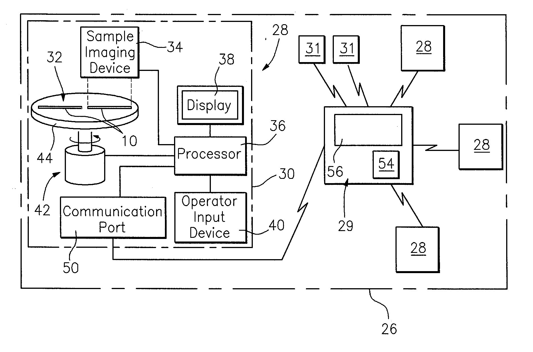
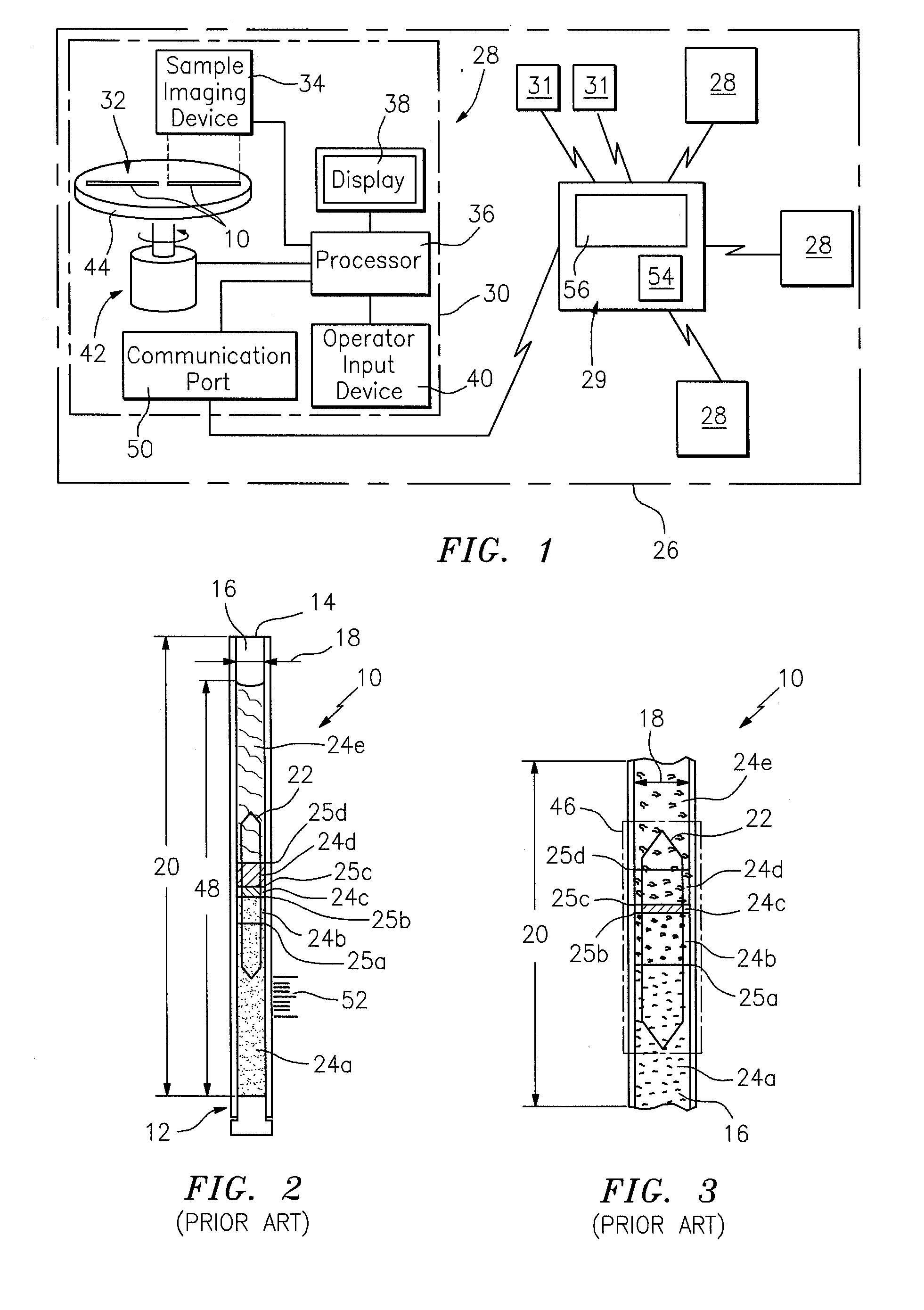
[0033]In the operation of the present system, unprocessed image signals are sent from the analysis device 28 to the remotely located analysis station 29. In this embodiment, the operator of the analysis device 28 images a centrifuged sample using the analysis device 28, and the “unprocessed” image of the centrifuged sample is sent to the remotely located analysis station 29. The remote analysis station 29 may be operated by a technician sufficiently trained so that he or she may analyze the sample image in a non-CLIA waived setting. The processor 54 within the remote analysis station 29 uses image processing algorithms to analyze the sample bands 24 of interest, and produces information based on the physical characteristics of the different bands 24, as described above. The image of the bands 24 of interest within the centrifuged sample is displayed on the data display of the analysis station 29 to allow the technician to perform a visual analysis of the sample image. In this embodi...

second embodiment

[0034]In the operation of the present system, image signals produced by the sample imaging device 34 within the local analysis device 28 are at least partially processed within the local analysis device 28, and are subsequently sent to the remotely located analysis station 29 where a trained technician may analyze the processed results and the sample image. The analysis enabled by the remote analysis station 29 and the trained technician can serve a variety of different functions. For example, the display screen 56 of the remote analysis station 29 permits a trained technician to view the actual sample image, including substantially all of the radial width 18 and axial length 20 of the sample residing within the internal cavity 16 of the tube 10 in the region where the float 22 resides after centrifugation. The discerning eye of a trained technician can assess image variables that are not accounted for in even the most comprehensive automated system. Consequently, the ability of the...


PUM


Abstract

An apparatus for and method of analyzing hematologic samples deposited within a capillary tube is provided. The method includes the steps of: a) imaging a region of sample centrifuged within a capillary tube using a first analysis device, which region is defined by substantially all of the radial width and axial length of the sample residing within the internal cavity of the tube where the float resides after centrifugation, and producing signals representative of the image; b) communicating the signals representative of the image to a second analysis device independent of, and remotely located from, the first analysis device; c) processing the signals representative of the image using the second analysis device and producing analysis data based on the signals; and d) displaying the image of the region of the sample using the second analysis device.

Description

[0001]This application claims the benefit of U.S. Provisional Patent Application No. 61 / 305,449 filed Feb. 17, 2010 and U.S. Provisional Patent Application No. 61 / 351,138 filed Jun. 3, 2010, each of which applications is hereby incorporated by reference in its entirety.BACKGROUND INFORMATION[0002]U.S. Pat. Nos. 4,027,660; 4,091,659; 4,137,755; 4,209,226; 4,558,947; 4,683,579; 5,132,087; 5,888,184; and 6,441,890 describe methods and apparatus for hematological analysis using a capillary tube and a space occupying insert that floats on the centrifuged red blood cells thereby expanding the surrounding buffy coat and permitting the measurement and quantization of the blood's layers. This method permits the determination of a compete blood count (CBC) consisting of hematocrit, a hemoglobin determination, a total white blood cell count with the latter presented as a total and percent granulocytes and total and percent lymphocytes plus monocytes, as well as a platelet count and a mean red ...

Claims


Application Information

Patent Timeline
IPC IPC(8): G06K9/00
CPCB01L3/50215B01L2300/0838G01N15/042G01N2800/22G01N33/491G01N2015/045G01N15/05B01L9/065B01L2300/027B01L2300/0609B01L2300/0654G06T7/0012G06T2207/30024
Inventor LEVINE, JOSHUA D.LEVINE, ROBERT A.WARDLAW, STEPHEN C.STOUT, CRAIGCLIPPER, DAVID A.
Owner QBC DIAGNOSTICS LLC
Why Eureka
Try Eureka