Printing roll and method of producing the same

Inactive Publication Date: 2011-08-25
TOCALO CO LTD
View PDF6 Cites 23 Cited by
  • Summary
  • Abstract
  • Description
  • Claims
  • Application Information

AI Technical Summary

Benefits of technology

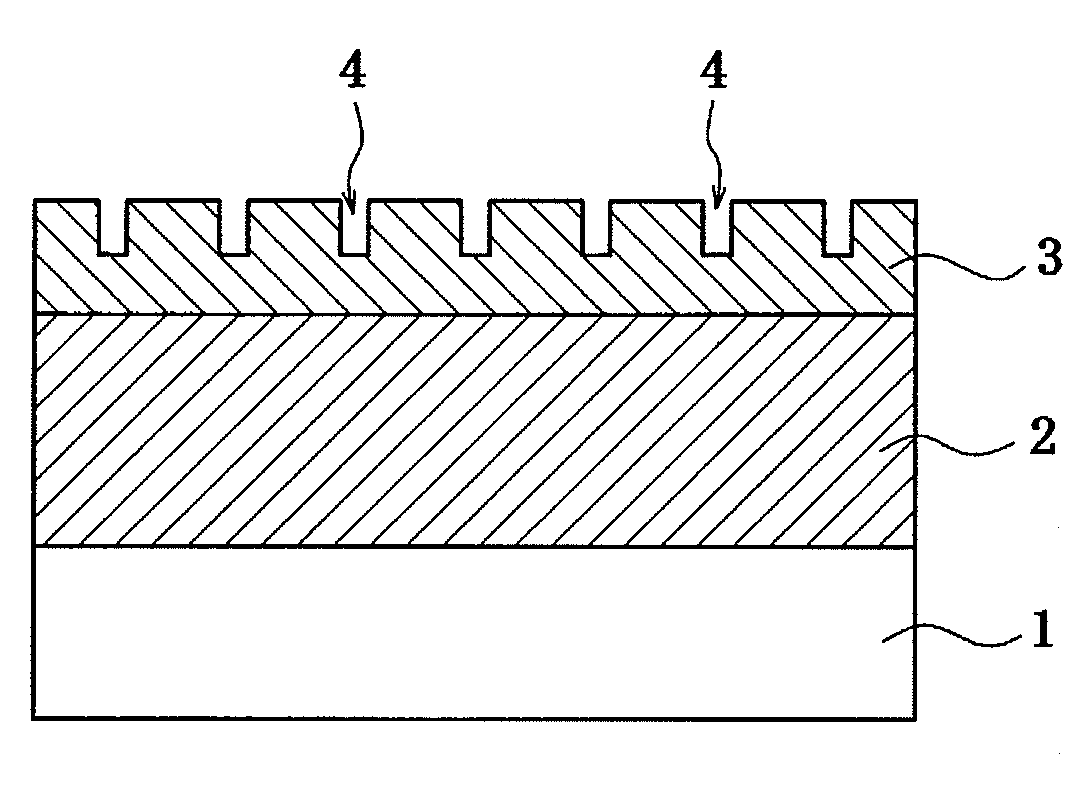
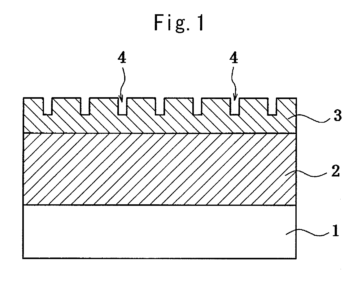
[0031]According to the invention, the aforementioned DLC film is used as an image forming layer of the printing roll or an engraved layer of concave portions for printing image area, so that the following effects can be expected:
[0032](1) Since the DLC film is typically hard and excellent in the abrasion resistance, when it is used as an image forming layer of the printing roll, laser beam-engraved grooves as a concave portion for printing image area (engraving surface) can be used over a long time of period without losing the shape;
[0033](2) The DLC film having laser beam-engraved grooves as the concave portion for printing image area has a smooth surface and is excellent in the abrasion resistance, so that it is small in the contact resistance with a printing paper and can increase the printing rate;
[0034](3) When the surface of the DLC film is engraved by laser beams to form the concave portions for printing image area, portions irra

Problems solved by technology

The solvents for the oil-based ink such as toluene, xylene, methyl ethyl ketone and the like are strong in the irritating odor, low in the flash point and high in the volatility, high in the risk of ignition and explosive and are absorbed by human bodies to induce health damage, so that they have significant problems in both of the safety and health.
However, papers printed by the oil-based ink are excellent in the gloss and beauty in the appearance, so that they are widely put into practice and can not be

Method used


Image

  • Printing roll and method of producing the same
  • Printing roll and method of producing the same
  • Printing roll and method of producing the same

Examples


example 1

[0162]In this example, a coating is formed on an aluminum substrate by various methods, and thereafter a DLC film is formed on the surface of the coating, and then the adhesion strength of the DLC film is measured by a scratch test defined according to an adhesion test method of thin film on glass substrate of JIS R3255.

[0163](1) Substrate

[0164]As a test piece substrate is used aluminum of 1050 grade defined in JIS H4000, which is cut into a test specimen of a size having width 50 mm×length 70 mm×thickness 5 mm.

[0165](2) Film Forming Method and Kind of Coating

[0166]Onto one-side surface of the above A1 test specimen is formed a coating as a ground layer for DLC film by the following film forming method.

[0167](i) Spraying method: WC-12 mass % Co, WC-20 mass % Ni-7 mass % Cr, TiC-20 mass % Ni, Cr3C2-20 mass % Ni-7 mass % Cr, Cu, Ni, Cr

[0168]Only Cr is by atmospheric plasma method, and others are by a high-speed flame spraying method, and the thickness of each film is 50 μm.

[0169](ii) ...

example 2

[0182]In this example, water-wetted state of DLC film co-precipitated with various metal oxides is examined, while the soundness of the DLC film is evaluated by subjecting the test specimen formed with the DLC film at a folded state of 90° to a salt spray test.

[0183](1) Spray Coating as a Test Substrate

[0184]As a test substrate is used SK steel, from which is cut out a test specimen having a size of width 30 mm×length 70 mm×thickness 3 mm, and only one-side surface thereof is roughened by plasma working and thereafter a coating of WC-20Ni-7Cr (numeral value is mass %) is formed at a thickness of 80 μm by high-speed flame spraying method. Further, the surface is subjected to finish polishing of Ra: 0.5-0.8 μm.

[0185](2) Properties of DLC Film

[0186]The following metal is co-precipitated into the DLC film over a full surface of the spray coating in the test specimen and then oxidized by an oxygen plasma treatment to form an oxide film having a thickness of 3 μm.

[0187](a) Kind of co-prec...

example 3

[0197]In this example, lipophilicity (hydrophobicity) and hydrophilicity (lipophobicity) are given to the DLC film according to the invention to research wetting state of water and oil against the film surface.

[0198](1) Test Substrate and Spray Coating

[0199]As a test substrate is used SUS 304 steel, from which is cut out a test specimen having a size of width 50 mm×length 100 mm×thickness 3.2 mm, and thereafter only one-side surface thereof is subjected to a plasma roughening treatment and then a WC-12 mass % Co cermet coating of 100 μm in thickness is formed on the roughened surface by a high-speed flame spraying method. Further, the surface of the spray coating is finished to Ra: 1.1-1.4 μM and Rz: 5-9 μm.

[0200](2) Properties of DLC Film

[0201]On the surface of the spray coating is formed a DLC film at a thickness of 5 μM, and then the DLC film is changed into hydrophilicity by subjecting to a treatment as mentioned below:

[0202](a) hydrophobic DLC film: film comprising hydrogen con...


PUM

PropertyMeasurementUnit
Percent by massaaaaaaaaaa
Thicknessaaaaaaaaaa
Pressureaaaaaaaaaa

Abstract

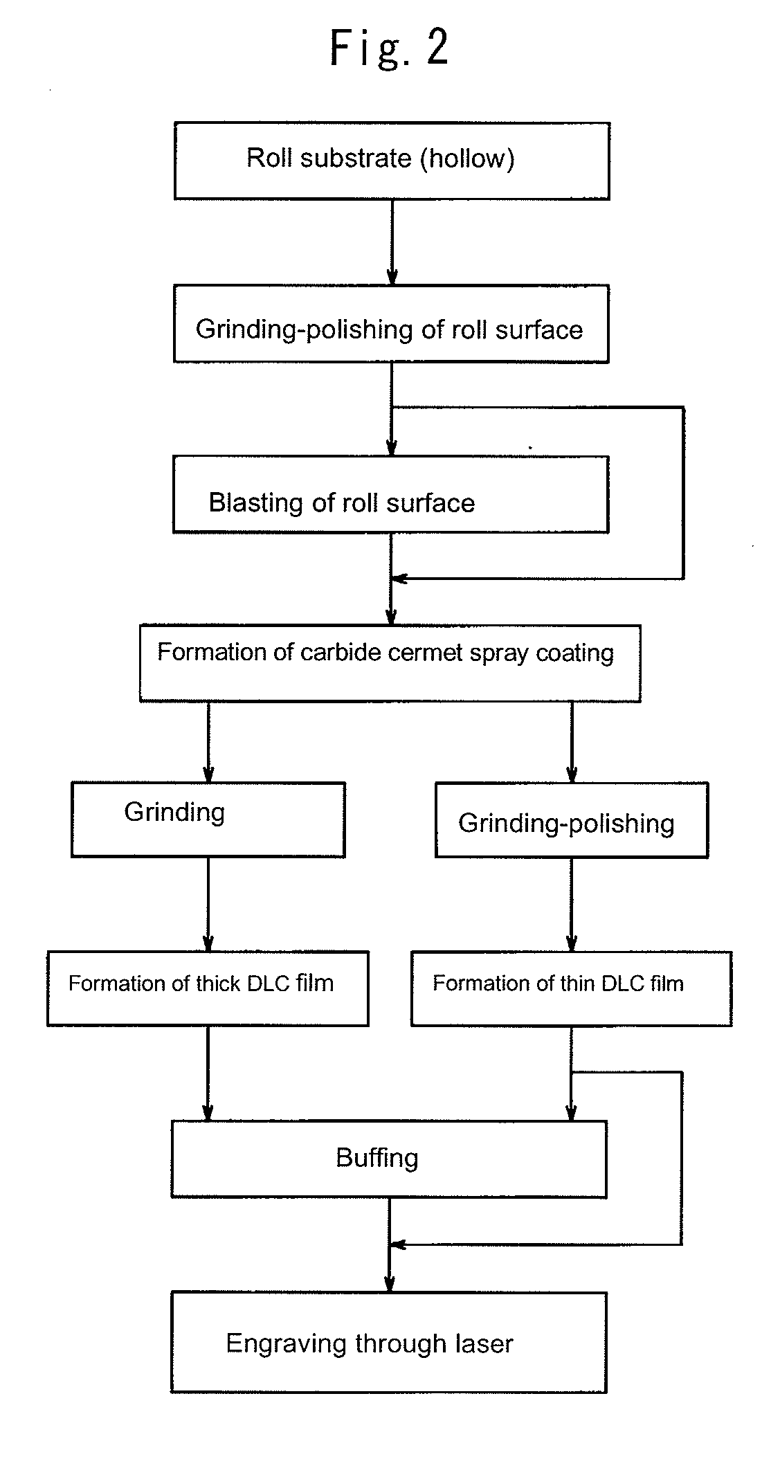
In order to propose a dry process technique of producing a printing roll having safe and beauty concave portions for printing image area without discharging environmental contaminating substance and a new technique for improving quality of printed matters, this invention is to provide a printing roll with DLC film layer in which laser beam-engraved grooves as concave portions for printing image area are formed on a carbide cermet spray coating formed on a surface of a roll substrate, and a method wherein a carbide cermet spray coating is formed on a surface of a roll substrate roughened by a blast treatment, the surface of the carbide cermet spray coating is ground or ground-polished, then a DLC film is formed on the ground or ground-polished surface and thereafter laser beam-engraved grooves are formed on the surface of the DLC film as a concave portion for printing image area.

Description

TECHNICAL FIELD[0001]This invention relates to a printing roll such as gravure engraving roll or the like, which is provided by directly forming laser beam-engraved grooves as a concave portion for printing image area on a surface of a diamond-like carbon membrane as an outermost layer, and a method for producing the same.RELATED ART[0002]Generally, the printing system can be divided into five systems of letterpress, lithography, intaglio, stencil and non-plate. The printing roll aimed at the present invention, for example, gravure engraving roll belongs to the intaglio, and is used in a printing system wherein an ink adhered to concave portions for printing image area are transferred to a paper after the ink is scraped out from non-image area. As a printing surface, those having 175 screening lines (printing elements) per 1 inch and a depth of a concave portion (cell) of about 2.5-30 μm are frequently used.[0003]On the other hand, almost of printing inks are oil-based or water-base...

Claims


Application Information

Patent Timeline
IPC IPC(8): B41F13/10B41C3/00
CPCB41C1/05B41N1/22B41N1/20B41N1/12B24C1/04
Inventor HARADA, YOSHIOTERATANI, TAKEMA
Owner TOCALO CO LTD
Why Eureka
Try Eureka