

Fuel cell electrolyte membrane
a fuel cell and electrolyte technology, applied in the field of electrolyte membrane for fuel cells, can solve the problems of electrolyte membrane mechanical deformation, decrease in power generation performance, and inflow and outflow of water, and achieve the effect of preventing a change in the dimensions and reducing the size of the electrolyte membran
- Summary
- Abstract
- Description
- Claims
- Application Information
AI Technical Summary
Benefits of technology
Problems solved by technology
Method used
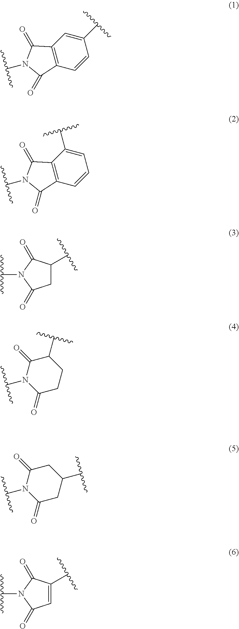
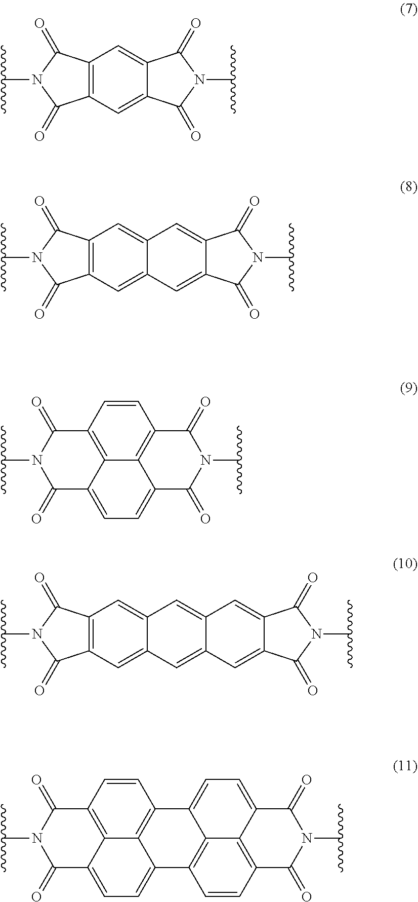
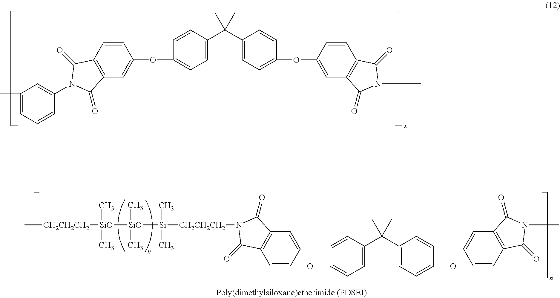
Image

Examples
example 1
[0049]A semi-transparent flexible electrolyte membrane was obtained by the following method. That is, 0.05 g (molecular weight of 20,000; 5 parts by weight) of PDSEI and 0.95 g (95 parts by weight) of Nafion (trade name; by DuPont) which is a type of perfluorocarbon sulfonic acid type resin was dissolved in 18 mL of DMA in a nitrogen atmosphere in an eggplant flask, and the resultant liquid solution was agitated for 2 hours at room temperature in a nitrogen atmosphere. After agitation, the agitator is extracted and the liquid solution was cast onto a glass petri dish, where it was left for 6 hours at 80° C. under a flow of nitrogen, whereupon a wet gel membrane was obtained. Then to remove any solvent remaining in the wet gel membrane, the wet gel membrane was dried under reduced pressure for 2 hours in a vacuum at 120° C., whereupon the semi-transparent flexible electrolyte membrane was obtained.
example 2
[0050]A second semi-transparent flexible electrolyte membrane was obtained by the same method and under the same conditions as in Example 1, except that 0.2 g (molecular weight of 20,000; 20 parts by weight) of PDSEI was used instead of 0.05 g (molecular weight of 20,000; 5 parts by weight), and 0.8 g (80 parts by weight) of Nafion (trade name; by DuPont) was used instead of 0.95 g (95 parts by weight).
example 3
[0051]A third semi-transparent flexible electrolyte membrane was obtained by the same method and under the same conditions as in Example 1, except that 0.3 g (molecular weight of 20,000; 30 parts by weight) of PDSEI was used instead of 0.05 g (molecular weight of 20,000; 5 parts by weight), and 0.7 g (70 parts by weight) of Nafion (trade name; by DuPont) was used instead of 0.95 g (95 parts by weight).
PUM
| Property | Measurement | Unit |
|---|---|---|
| bond distance | aaaaa | aaaaa |
| bond angle | aaaaa | aaaaa |
| bond distance | aaaaa | aaaaa |
Abstract
Description
Claims
Application Information