Dye-sensitized solar cell

Inactive Publication Date: 2011-09-15
DAI NIPPON PRINTING CO LTD
View PDF7 Cites 4 Cited by
  • Summary
  • Abstract
  • Description
  • Claims
  • Application Information

AI Technical Summary

Benefits of technology

[0027]The present invention provides the conductive base material for dye-sensitized solar cell comprising a first metal layer and a second metal layer, which makes it possible to provide a dye-sensitized solar cell that has high resistance to corrosion by iodide ions contained in an electrolyte layer thereof and is less likely to be degraded with time. Further, the conductive b

Problems solved by technology

However, these solar cells have problems such as high production cost, etc.
However, a dye-sensitized solar cell using a titanium base material as an electrode layer has a problem of high production cost.
In order to solve such a problem, there has been a demand for a cheap metal base material that can be used as the electrode layer instead of a titanium base material, but many metal base materials are inferior in resistance to corrosion by iodide ions to a titanium base material.
However, the electrode layer disclosed in JP-A No. 2007-87744 uses a nickel plate having a thickness of 1 mm, and therefore there is a problem that electrical resistance caused by the nickel plate is high, which reduces the fill factor and power generation efficiency of a dye-sensitized solar

Method used


Image

  • Dye-sensitized solar cell
  • Dye-sensitized solar cell
  • Dye-sensitized solar cell

Examples


example 1

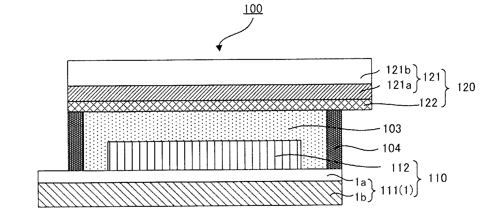
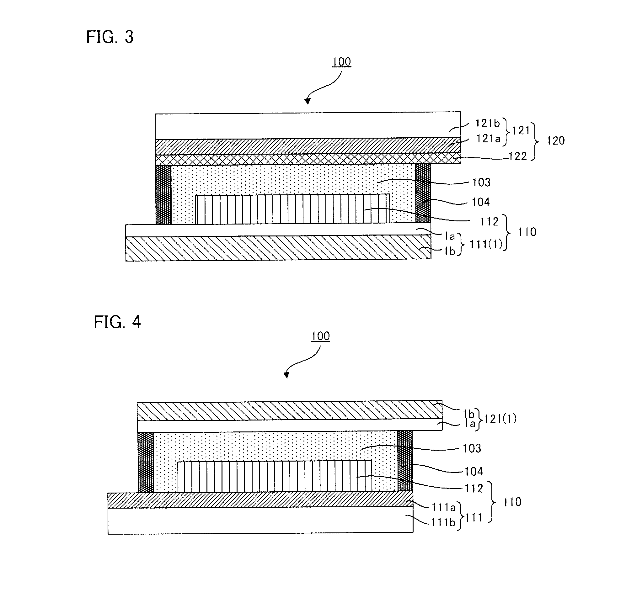
[0232]A 50 μm-thick stainless steel base material (SUS304, specific resistance: 0.7×10⁻⁶ Ω·m) was prepared as a first metal layer, and a conductive base material for dye-sensitized solar cell was obtained by forming a 15 nm-thick Cr layer as a second metal layer on the stainless steel base material by vacuum vapor deposition.

[0233]An ink was prepared by dispersing TiO2 fine particles (P25™ manufactured by Nippon Aerosil Co., Ltd.) in ethanol, and a coating liquid for forming a porous layer was obtained by adding polyvinyl pyrrolidone (K-90™ manufactured by Nippon Shokubai Co., Ltd.) to the ink to achieve a solid content of 5%. Then, the coating liquid for forming a porous layer was applied with a doctor blade on an area of 10 mm×10 mm on the Cr layer of the conductive base material for dye-sensitized solar cell used as a first electrode base material and was then dried at 120° C. to obtain a 7 μm-thick layer for forming a porous layer. Then, a pressure of 0.1 t / cm was applied onto t...

example 2

[0238]A dye-sensitized solar cell was produced in the same manner as in Example 1 except that the second metal layer was changed to a 50 nm-thick Cr layer.

example 3

[0239]A dye-sensitized solar cell was produced in the same manner as in Example 1 except that the second metal layer was changed to a 15 nm-thick Ti layer.


PUM

PropertyMeasurementUnit
Nanoscale particle sizeaaaaaaaaaa
Electrical resistivityaaaaaaaaaa

Abstract

An object of the present invention is to provide a conductive base material for dye-sensitized solar cell and a transparent conductive base material for dye-sensitized solar cell which, when used as electrode base materials of a dye-sensitized solar cell, have high resistance to corrosion by iodide ions contained in an electrolyte layer and can prevent a reduction in the fill factor and conversion efficiency of the dye-sensitized solar cell to achieve high power generation efficiency, a dye-sensitized solar cell and a dye-sensitized solar cell module using such conductive base materials. To attain the object, provided is the conductive base material for dye-sensitized solar cell comprising: a first metal layer made of a metal having a specific resistance of 6×10⁻⁶ Ω·m or less; and a second metal layer formed on the first metal layer, made of any one of metals of Ti, Cr, Ni, Mo, Ta, W, Nb, and Pt, and having a thickness of 500 nm or less.

Description

BACKGROUND OF THE INVENTION[0001]1. Field of the Invention[0002]The present invention relates to a conductive base material for dye-sensitized solar cell, a transparent conductive base material for dye-sensitized solar cell, a dye-sensitized solar cell, and a dye-sensitized solar cell module.[0003]2. Description of the Related Art[0004]In recent years, environmental issues such as global warming believed to be caused by an increase in CO2 have become serious, and therefore measures have been taken to deal with such environmental issues on a worldwide basis. Particularly, research and development of solar cells utilizing the energy of sunlight has been actively conducted as clean energy sources that have a low impact on the environment. As such solar cells, monocrystal silicon solar cells, polycrystal silicon solar cells, amorphous silicon solar cells, and compound semiconductor solar cells, and the like have already been put to practical use. However, these solar cells have problems...

Claims


Application Information

Patent Timeline
IPC IPC(8): H01L31/042H01L31/0224B32B15/00B32B15/20B32B7/00
CPCB32B15/01B32B15/18B32B15/20B32B2457/12Y10T428/12743H01G9/2059Y02E10/542Y10T428/12771Y10T428/12451H01G9/2031B32B15/02B32B15/043B32B3/26B32B2264/102B32B2307/202B32B2307/412B32B2307/714B32B2307/732
Inventor OBONAI, NAOHIROSASAKI, MIHO
Owner DAI NIPPON PRINTING CO LTD
Why Eureka
Try Eureka