Method and apparatus for interferometry

a technology of interferometry and methods, applied in the field of methods and apparatus for interferometry, can solve the problems of inability to scale up the resolution capability and depth measurement range of the applicator, the multiplicity of technical problems, and the high cost, and achieve the effect of high measurement and scanning accuracy and high degree of technical complexity

Inactive Publication Date: 2011-09-29
UNIV STUTTGART
View PDF7 Cites 150 Cited by
  • Summary
  • Abstract
  • Description
  • Claims
  • Application Information

AI Technical Summary

Benefits of technology

[0020]The object of the present invention is to provide interferometry which can be adapted over a wide scale, with high measurement and scanning accuracy and with the measurement being highly robust.

Problems solved by technology

These approaches cannot be scaled to a major extent in terms of resolution capability and depth measurement range in the direction of coarser scales since these methods are in general very closely linked to the magnitude of the light wavelength that is used.
Short-coherence interferometry in the infrared spectral range generally leads to a multiplicity of technical problems and to high costs.
In many cases, for example for use in an endoscope, this can be achieved only with a comparatively high level of technical complexity, and with comparatively high costs.
White-light interferometry sensors based on the approaches described in [1]-[7] also in general do not allow measurements, for arrangements in which the volume must be greatly minimized, on objects with distances between the object and the sensor in the region of one or more meters, since during the measurement, the optical path length in the reference arm must at least once be made equal to the optical path length in the object arm.
Even with folded arrangements, this generally leads to the sensor having a considerable physical volume.
A rapid single-shot measurement over an area is feasible only with a very high level of technical complexity, since an object is detected laterally in a serial form.
The necessity to use a spectrometer in the optical measurement system in each case here means, however, that an object cannot be recorded over an area or as an image at one time, but in general can be recorded only point-by-point; the detection of an object over an area must therefore be carried out laterally and in a serial form.
Furthermore, however, these approaches do not allow application to the measurement of macroscopic objects, but are restricted for financial reasons to the measurement of comparatively small objects.
In fact, it is not even possible to measure objects with a large depth extent and a long distance, using approaches such as these.
However, this approach cannot be used to completely measure an object with a comparatively great depth extent if the aim is to use a comparatively large numerical aperture for object imaging, in order to achieve high lateral resolution.
Furthermore, if this approach is to be used for rapid measurement of an object with a comparatively large depth extent, it is absolutely essential to use either a high-speed camera or a short-pulse frequency comb laser source, or a rapid shadowing apparatus since, when the frequency intervals of the frequency comb laser are tuned through rapidly as is then required this also results in a high phase angle rate in the interference phenomenon to be scanned at the output of the interferometer.
These means are either complex and costly or, in the end, lead to signals with a rather poor signal-to-noise ratio for detection of the interference phenomenon.
Furthermore, in this case, it is actually not possible to scale the measurement method for a large depth measurement range.
In this case, it is impossible to record objects using confocal filtering.
In this case, the measurement method cannot be scaled for a large depth measurement range.

Method used


Image

  • Method and apparatus for interferometry
  • Method and apparatus for interferometry
  • Method and apparatus for interferometry

Examples


Embodiment Construction

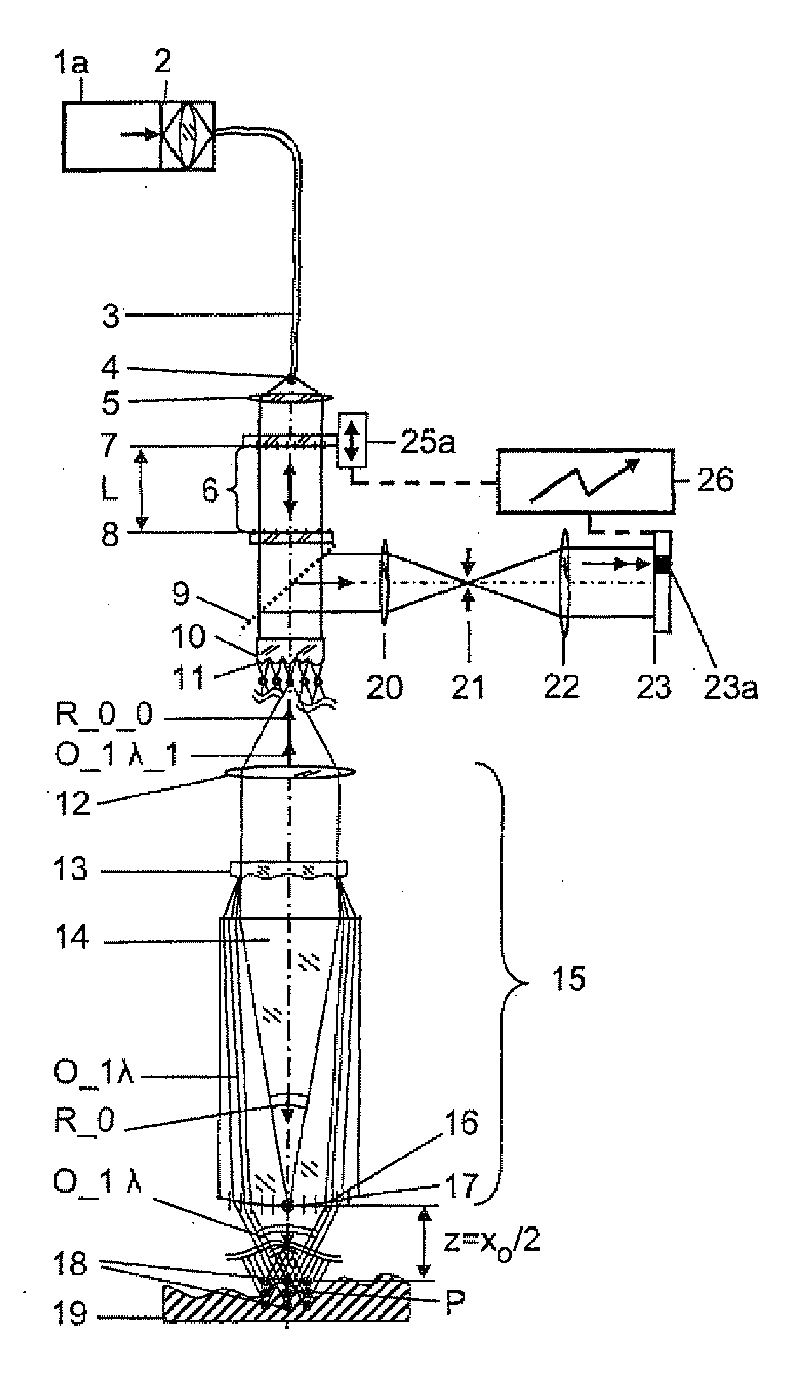
[0222]The invention will be described by way of example with reference to the preferred embodiments illustrated in FIGS. 1 to 26. In this case, the term light is always used synonymously for electromagnetic radiation from the Terahertz, through the infrared, to the deep UV spectrum.

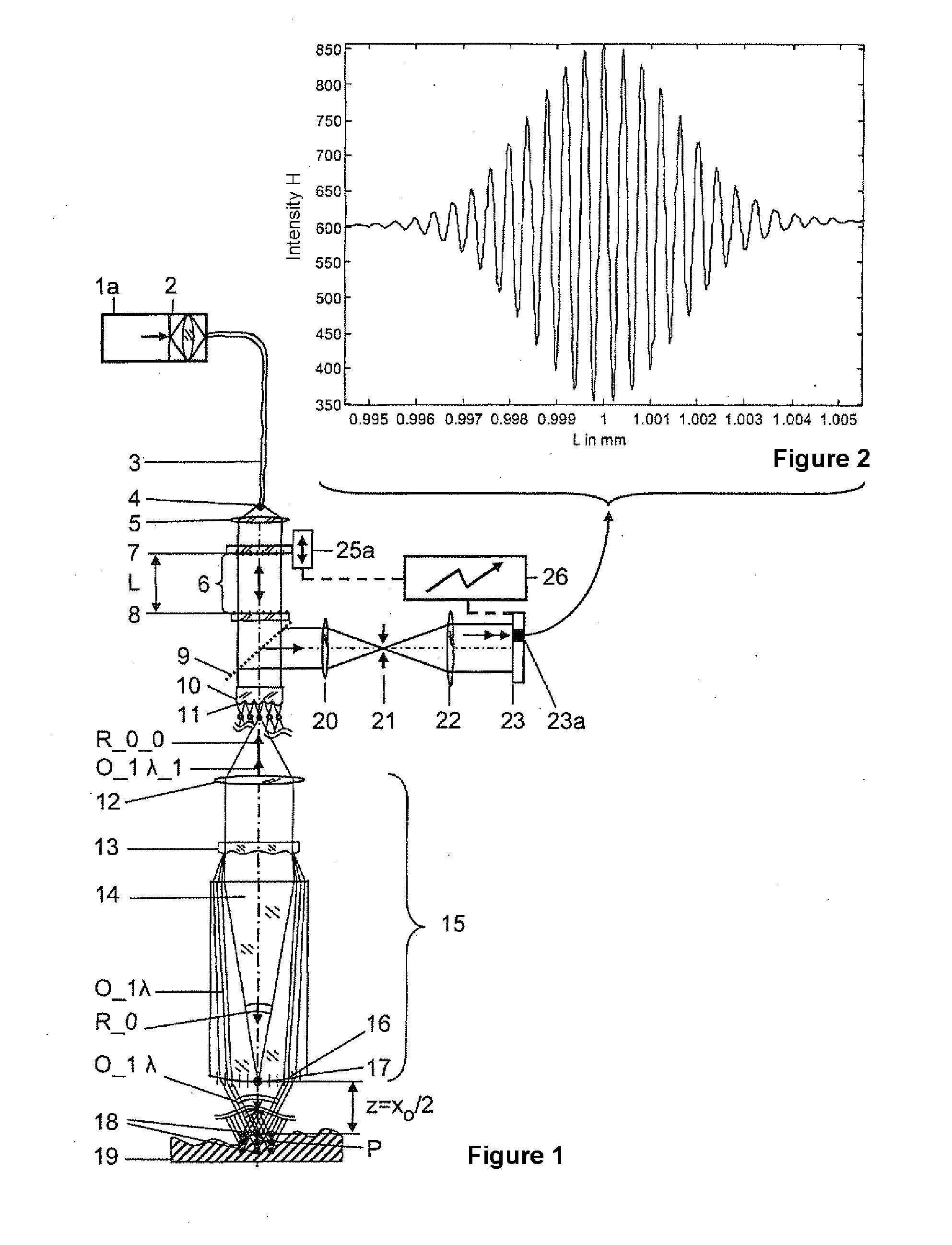
[0223]FIG. 1 shows the sensor on the basis of a chromatic-confocal, spectral two-beam interferometer with a multi-beam interferometer arranged downstream from the light source, for a relatively small object field with respect to the focal length of the object-imaging system. The light from an optically powerful, fiber-coupled superluminescence diode 1a in the near infrared range is injected by means of focusing optics 2 into a single-mode fiber 3, emerges from this single-mode fiber 3 again at its outlet 4, is collimated by an objective lens 5 and is passed into a Fabry-Perot interferometer 6, in this case in the form of a Fabry-Perot interferometer 6 with the mirror separation L, with which a piezo-contr...


PUM


Abstract

A method and an arrangement are provided for scalable confocal interferometry for distance measurement, for 3-D detection of an object, for OC tomography with an object imaging interferometer and at least one light source. The interferometer has an optical path difference not equal to zero at each optically detected object element. Thus, the maxima of a sinusoidal frequency wavelet, associated with each detected object element, each have a frequency difference Δf_Objekt. At least one spectrally integrally detecting, rastered detector is arranged to record the object. The light source preferably has a frequency comb, and the frequency comb differences Δf_Quelle are changed in a predefined manner over time in a scan during measuring. In the process, the frequency differences Δf_Quelle are made equal to the frequency difference Δf_Objekt or equal to an integer multiple of the frequency differences Δf_Objekt at least once for each object element.

Description

BACKGROUND OF THE INVENTION[0001]1. Field of the Invention[0002]The invention relates to a method and to an arrangement for scalable confocal interferometry for distance measurement, for 3-D detection of an object, for OC tomography with an object imaging interferometer and at least one light source.[0003]2. Description of the Related Art[0004]The sequential recording of data from different depths of the object space by focusing through plays a functionally important role, as is known, for microscopic white-light interferometry. Reference to this can be found in the following documents:[0005][1] Balasubramanian N: Optical system for surface topography measurement. U.S. Pat. No. 4,340,306 (1982),[0006][2] Kino G S, Chim S: Mirau correlation microscope. Appl. Opt. 29 (1990) 3775-3783,[0007][3] Byron S L, Timothy C S: Profilometry with a coherence scanning microscope. Appl. Opt. 29 (1990) 3784-3788,[0008][4] Dresel T h, Häusler G, Venzke H: Three-dimensional sensing of rough surfaces b...

Claims


Application Information

Patent Timeline
Patent Type & Authority Applications(United States)
IPC IPC(8): G01J3/45
CPCG02B21/0056G01B9/02004G01B9/02008G01B9/02057G01B9/02091G01B9/02042G01B9/02036G01B2290/25G01B2210/50G01B2290/30
Inventor KOERNER, KLAUSOSTEN, WOLFGANG
Owner UNIV STUTTGART
Why Eureka
Try Eureka