Mass analyzer

Active Publication Date: 2011-10-06
SHIMADZU RES LAB SHANGHAI
View PDF3 Cites 45 Cited by
  • Summary
  • Abstract
  • Description
  • Claims
  • Application Information

AI Technical Summary

Benefits of technology

[0012]One objective of the present invention is to improve the ion detection efficiency of non-destructive ion detection in a multiturn type mass spectrometric analyzer.
[0017]According to another aspect of present invention there provides a method of mass spectrometric analysis using a multi-turn flight tube analyzer, including: disposing electrostatic reflectors or electrostatic deflector in the analyzer, so as to enable pulsed ions to be analyzed to move therein periodically for multiple times, form time focusing in a partial region thereof, and form an confined ion beam in space; enabling the ion beam to pass through multiple tubular image current detectors arranged in series along an axial direction of the ion beam periodically; using a low-noise electronic amplification device to detect image currents picked up by the multiple tubular detectors differentially; and using a digital conversion method to perform data conversion on an amplified signal to acquire a mass spectrum.
[0020]Compared with the prior art, the present invention has the following obvious advantages by adopting the above technical solutions.
[0023]3. In case a row of multiple cylinder detection electrodes are positioned in series coaxially, and ions are injected from one end, a pulse image current is induced on each cylinder at different timing. Differential signal between adjacent cylinder detectors can be recorded, and the differential signal is then added up to the differential signal of next adjacent detection electrodes, and so on. A pulse signal sequence corresponding to time is obtained where high frequency components are significantly enhanced compared with high frequency components detected by a single detection cylinder. The high frequency components have a close relationship with the velocity of the pulsed ions, a mass spectrum can be acquired by performing proper conversion on the signal, and the signal-to-noise ratio can be increased.

Problems solved by technology

Definitely, the ions are eventually led out to undergo destructive detection after a voltage of one of the reflectors is switched.
A problem of the mass spectrometer is that: if a mass range of measured ions is large, the motion cycle time of ions of light mass is obviously shorter than that of ions of heavy mass, and during to and fro movement, the ions of light mass will overtake the ions of heavy mass by one or more turns, so that in the detected mass spectrum, ions of different mass overlap.
Therefore, the mass spectrometer can only analyze a small mass range of ions.
However, the aforementioned devices also have the problem of small mass range.
Although we can use a mass pre-selection method to limit the mass range of ions to entering the analyzer, and then stitch many mass spectra of a small range into a mass spectrum of a wide mass range by software, many difficulties will be encountered during practical operation, for example, mass errors occur at joints.
It is neither easy to introduce an internal mass standard for calibration, and high-precision mass analysis cannot be achieved.
However, the method requires spectrum acquisition to be performed on a sample for multiple times in different instrument settings, and during the multiple times of the spectrum acquisition, it must be ensured that components of the sample do not change, which obviously brings difficulties to application, and affects the efficiency of analysis.
However, after multiple times of to and fro movement, the ions in an ion group disperse gradually due to differences in their initial kinetic energy, the image current signal broadens in time and decreases in intensity, until becoming undetectable eventually.
However, when the bunching based on the coulomb interaction is applied to a mass spectrometer for analyzing a complex ion combination, and especially in the presence of many satellite peaks, large peaks hijack small peaks, which affects resolving power and reduces the precision of the analyzer.

Method used


Image

  • Mass analyzer
  • Mass analyzer
  • Mass analyzer

Examples


Embodiment Construction

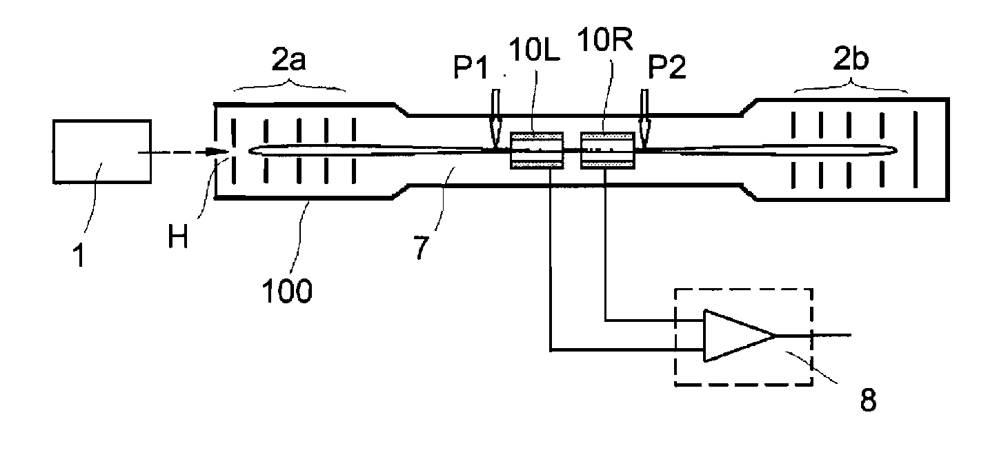
[0036]First, a basic structure of a reciprocating multi-reflection flight tube is used to describe an analyzer according to an embodiment of the present invention.

[0037]A flight tube 100 in FIG. 1 includes two opposite reflectors 2a and 2b, a pulsed ion beam Ib generated by the pulsed ion source 1 can be introduced through a small hole H in the end electrode of the reflectors. After ions are introduced, some electrode voltages in the reflectors 2a should be restored to voltage values of normal reflective mode. In this way, the ions can be reflected continuously between the two reflectors.

[0038]For a positive ion mode, positive voltages need to be applied on some electrodes in the reflectors. The electric potential in the reflectors may be as high as thousands of volts or tens of thousands of volts relative to a drift space 7, so that the ions have kinetic energy ranging from thousands of electron-volts to tens of thousands of electron-volts when reflected to the drift region 7. The ...


PUM


Abstract

A mass spectrometric analyzer and an analysis method based on the detection of ion image current are provided. The method in one embodiment includes using electrostatic reflectors or electrostatic deflectors to enable pulsed ions to move periodically for multiple times in the analyzer, forming time focusing in a portion of the ion flight region thereof, and forming an confined ion beam in space; enabling the ion beam to pass through multiple tubular image current detectors arranged in series along an axial direction of the ion beam periodically, using a low-noise electronic amplification device to detect image currents picked up by the multiple tubular detectors differentially, and using a data conversion method, such as a least square regression, to acquire a mass spectrum.

Description

FIELD OF THE INVENTION[0001]The present invention relates generally to the field of mass spectrometric analysis technologies, and more particularly to a mass spectrometric analyzer that utilizes an image current to perform non-destructive detection on high-velocity moving ions.BACKGROUND OF THE INVENTION[0002]Many common mass spectrometer products have been developed since the development of mass spectrometry. In an existing mass spectrometer, methods for detecting an ion signal are categorized into: a destructive detection type and a non-destructive detection type. In destructive detection, ions after passing through an analyzer are received by a Faraday cup or a dynode. Charges of the ions are transformed into a current on the Faraday cup, and are amplified by a circuit, or ions are firstly converted to electron and then multiplied by the dynode and their charges are detected. After detection, the ions are neutralized to disappear on the Faraday cup or the dynode. Conventionally, ...

Claims


Application Information

Patent Timeline
IPC IPC(8): H01J49/40
CPCH01J49/4245H01J49/027H01J49/0036
Inventor DING, LI
Owner SHIMADZU RES LAB SHANGHAI
Why Eureka
Try Eureka