Degradable cage for bone fusion

a bone fusion and cage technology, applied in the field of cages, can solve the problems of reducing the efficacy of interbody fusion, increasing the incidence of postoperative complications, and synovitis and the lymphatic spread of non-absorbable polymer debris, so as to improve the bioactivity of spinal implants, improve the effect of fusion efficiency and superior binding capacity

Inactive Publication Date: 2011-11-17
DEPUY SYNTHES PROD INC
View PDF17 Cites 52 Cited by
  • Summary
  • Abstract
  • Description
  • Claims
  • Application Information

AI Technical Summary

Benefits of technology

[0013]The structurally tailored design that is able to fulfill the mechanical load bearing requirements is incorporated with innovative mineralization processes to enhance the bioactivity of the spinal implant. The ...

Problems solved by technology

While current segmental spinal fusion relieves pain by eliminating spinal instability, complications associated with conventional metallic cages, including; difficulty of revisions, increased adjacent level disc disease due to increased loading, implant migration or failure, imaging artifacts, stress shielding, and limited bone grafting significantly reduce the efficacy of the interbody fusion.
However, since clinically reliable reports of using these cages are scarce, concerns still remain that synovitis and the lymphatic spread of non-absorbable polymer debris may be found after intra-articular procedures (see Cho et al., “Preliminary experience using a polyetheretherketone (PEEK) cage in the treatment of cervical disc disease”Neurosurgery 52(3):6932003 and Neurosurgery 51:1343 2002; and Parsons et al., “Carbon fiber debris within the synovial joint.
However, current metallic cages are associated with excessive rigidity that increases incidence of postoperative complications such as stress-shielding, the migration or dislodgement of the cage, pseudoarthrosis, or the combined adverse symptoms (see van Dijk et al.
Metallic cages can also interfere with visual assessment...

Method used


Image

  • Degradable cage for bone fusion
  • Degradable cage for bone fusion
  • Degradable cage for bone fusion

Examples


example

In Vivo Fusion Using Polycaprolactone Cages in a Large Animal Model

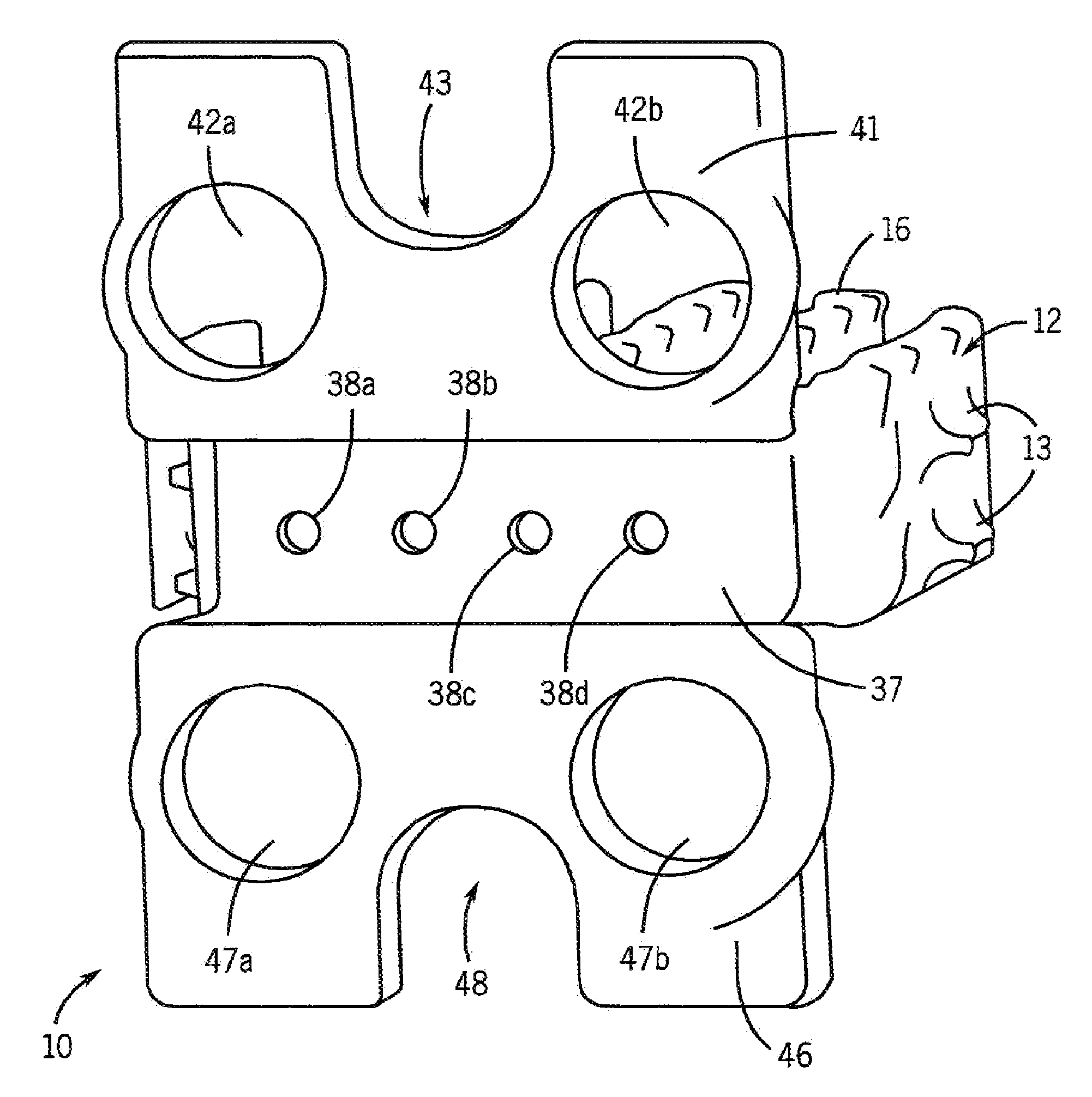
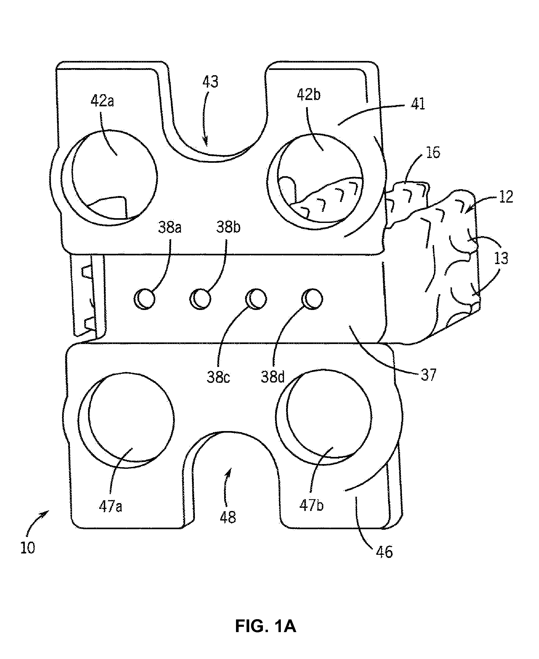
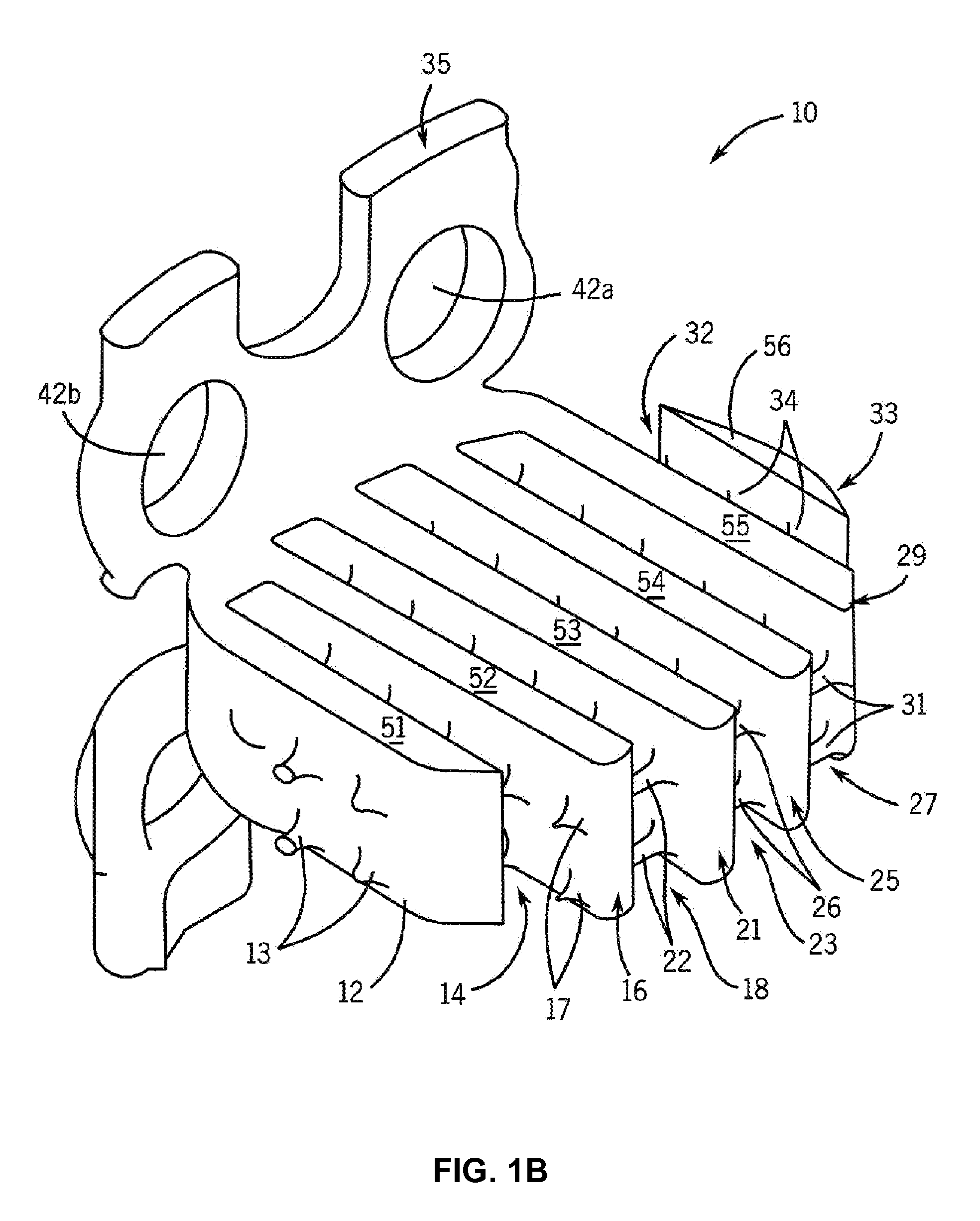
[0089]Cages were designed and constructed using the methods described above. FIG. 7 shows the design model of the cages, and FIG. 8 shows the constructed cage. The interbody portion was 5.3 mm thick, having “fingers” designed to withstand surgical implantation loading in addition to in vivo compression forces and bending moments (FIG. 7). The plate was designed with four screw holes for surgical attachment (FIG. 7). These fusion device sizes were similar to human cage designs, a rationale for using the pig as an animal model. The manufacturing process can readily build 30 cages per day on one machine. Manufacturing quality was assessed both non-destructively using micro-computed tomography (micro-CT) scanning and mechanical compression testing. Micro-CT analysis (FIG. 9) demonstrated fidelity of manufactured device to the design with a defect volume of less than 0.6%.

[0090]Some of the cages were coated with a 50-100 ...


PUM

PropertyMeasurementUnit
Microstructureaaaaaaaaaa
Biocompatibilityaaaaaaaaaa
Polymericaaaaaaaaaa

Abstract

A cage for facilitating fusion of bones, such as vertebrae, or fusion of adjacent bone surfaces is disclosed. In one form, the cage includes a plurality of spaced apart walls comprising a biodegradable polymeric material (e.g., polycaprolactone); an osteoconductive mineral coating (e.g., a calcium compound) on at least a portion of the walls; and a bioactive agent (e.g., a bone morphogenetic protein) associated with the polymeric material and/or the coating. The bioactive agent is present in amount that induces ossification between the bones or adjacent bone surfaces. The cage may also include a fixation plate connected to at least one of the walls.

Description

CROSS-REFERENCE TO RELATED APPLICATIONS[0001]This application is a continuation-in-part of application Ser. No. 11 / 927,322, filed Oct. 29, 2007, which claims the benefit of U.S. Provisional Application No. 60 / 855,235, filed Oct. 30, 2006.BACKGROUND OF THE INVENTION[0002]1. Field of the Invention[0003]This invention relates to cages for facilitating the fusion of adjacent bones or adjacent bone surfaces, and more particularly to degradable cages for spinal interbody fusion.[0004]2. Description of the Related Art[0005]Back pain resulting from instability of the spinal system is a rapidly growing condition in the United States. Spinal fusion procedures are expected to grow from over 400,000 procedures in 2004 to 550,000 procedures in 2010. This is driven by an aging population, increasing obesity, and increased patient education and awareness of the fusion procedures. While current segmental spinal fusion relieves pain by eliminating spinal instability, complications associated with co...

Claims


Application Information

Patent Timeline
IPC IPC(8): A61B17/88A61F2/44A61B17/70
CPCA61B17/7059A61K38/30A61F2002/2817A61F2002/30011A61F2002/30013A61F2002/30032A61F2002/30056A61F2002/30062A61F2002/30064A61F2002/3008A61F2002/30303A61F2002/30578A61F2002/30785A61F2002/30789A61F2002/30838A61F2002/30878A61F2002/30884A61F2002/30892A61F2002/30899A61F2002/3092A61F2002/4485A61F2210/0004A61F2310/00017A61F2310/00023A61F2310/00029A61F2310/00089A61F2310/00113A61F2310/00131A61F2310/00149A61F2310/00155A61F2310/00293A61F2310/00796A61F2310/0097A61F2310/00976A61K38/1825A61K38/1841A61K38/1858A61K38/1875A61F2/4455
Inventor MURPHY, WILLIAM L.LIN, CHIA-YINGLAMARCA, FRANKHOLLISTER, SCOTT J.
Owner DEPUY SYNTHES PROD INC
Why Eureka
Try Eureka