Treatment of natural gas feeds

a technology of natural gas feed and treatment process, which is applied in the direction of gaseous fuels, separation processes, membranes, etc., can solve the problems of large footprint and heavy weight of amine units, low separation efficiency of amine systems, and flow mal-distribution

Inactive Publication Date: 2011-12-01
UOP LLC
View PDF0 Cites 34 Cited by
  • Summary
  • Abstract
  • Description
  • Claims
  • Application Information

AI Technical Summary

Benefits of technology

[0006]The present invention provides a process for treating a natural gas stream comprising sending a natural gas stream to at least one membrane unit to produce a permeate stream containing a higher concentration of carbon dioxide than the natural gas stream and a retentate stream containing a lower concentration of carbon dioxide than the natural gas stream. Then the retentate stream is sent to a molecular sieve adsorbent bed to remove carbon dioxide and other impurities from the retentate stream to produce a natural gas product stream. The regeneration gas stream is sent through the molecular sieve adsorbent bed to desorb the carbon dioxide. The present invention provides two process flow schemes for natural gas treatment. In a first embodiment, the regeneration stream from the molecular sieve adsorbent beds is combined with the permeate stream from the membrane. Then the combined stream is sent to an absorbent column to remove carbon dioxide and other acid gases to produce a low acid gas concentration natural gas stream, which is sent to either the membrane or the molecular sieve adsorbent beds. The alternative process flow scheme for treating a natural gas stream comprises sending a natural gas stream to at least one membrane unit (first membrane unit) to produce a permeate stream containing a higher concentration of carbon dioxide than the natural gas stream and a retentate stream containing a lower concentration of carbon dioxide than the natural gas stream. Then the retentate stream is sent to the molecular sieve adsorbent beds to remove carbon dioxide and other impurities from the retentate stream to produce a natural gas product stream. The regeneration gas stream is sent through the molecular sieve adsorbent bed to desorb the carbon dioxide and then is sent with the carbon dioxide to at least another membrane unit (second membrane unit) to remove carbon dioxide and other impurities. The retentate stream from second membrane unit is sent to the molecular sieve adsorbent beds. The permeate streams from first and second membranes unit are combined and sent to an absorption column to remove carbon dioxide and other acid gases to produce a second natural gas product stream, which is sent to either the first membrane unit or the molecular sieve unit.

Problems solved by technology

For offshore FLNG service, however, there are at least two problems associated with use of a solvent process.
When an acid gas such as CO2 is present at an increased concentration in a natural gas feed, the amine absorption column diameter and the amine solvent circulation rate that is needed significantly increases, which results in large footprint and heavy weight of the amine unit.
Second, motion at high sea stages often generates flow mal-distribution inside the amine absorbers and stripping regenerators.
This flow mal-distribution results in low separation efficiency of the amine systems.
Hence, the natural gas product from the amine treatment may not be able to meet the specifications for acid gas content such as CO2 required for liquefaction processes.
CO2 is one of the contaminants with the highest concentration in the feed gas and its removal poses special challenges to the FLNG application.
The problem of pre-treatment can be said to be one of minimizing foot print and weight of the combined treatment train while maximizing the reliability of the treatment train.
However, for FLNG applications, motion at high sea stage often generates flow mal-distribution inside the amine absorber and stripping regenerator, which results in risk of not meeting the low CO2 concentration (<50 ppm) spec in the treated gas.

Method used


Image

  • Treatment of natural gas feeds
  • Treatment of natural gas feeds
  • Treatment of natural gas feeds

Examples


Embodiment Construction

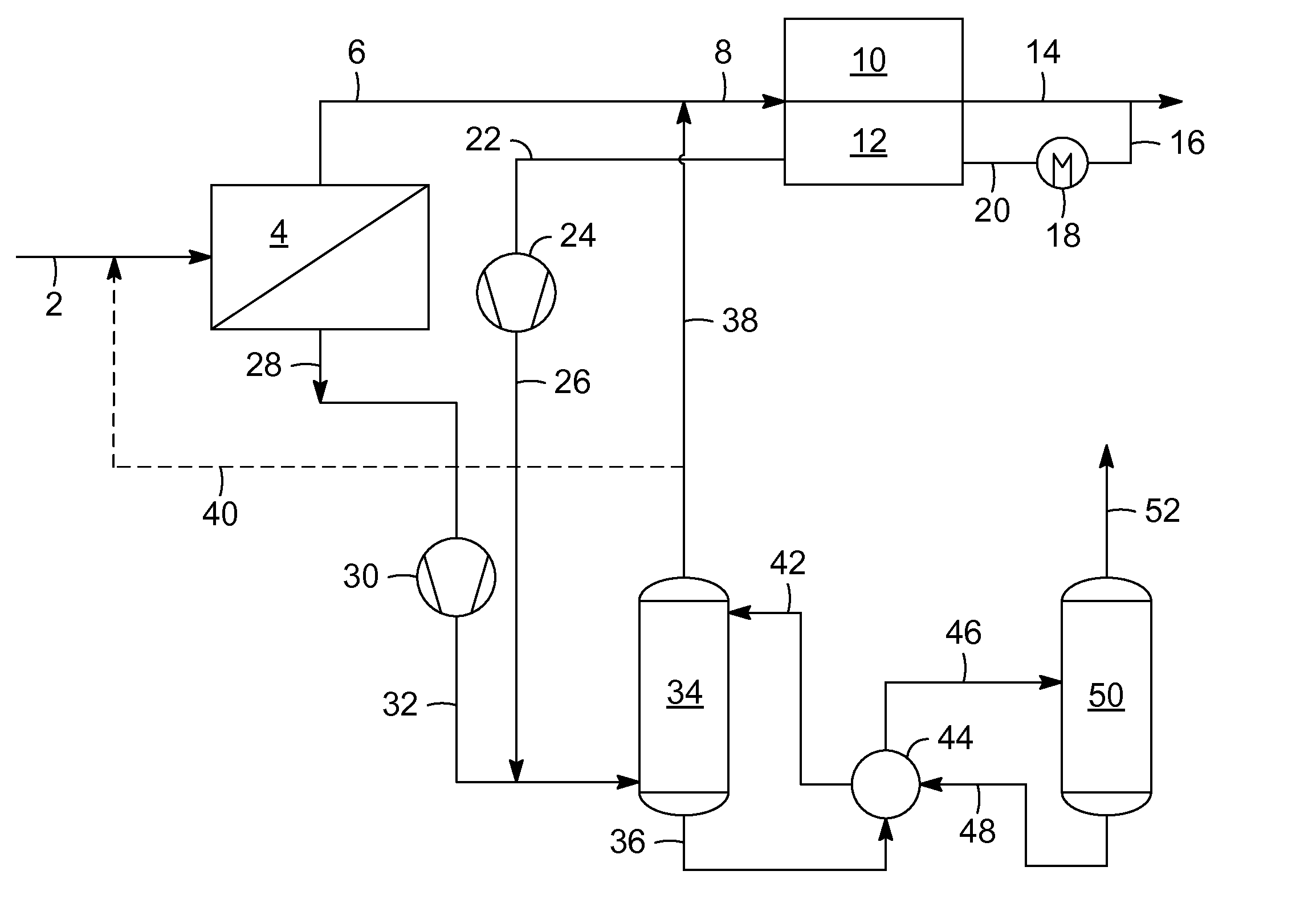
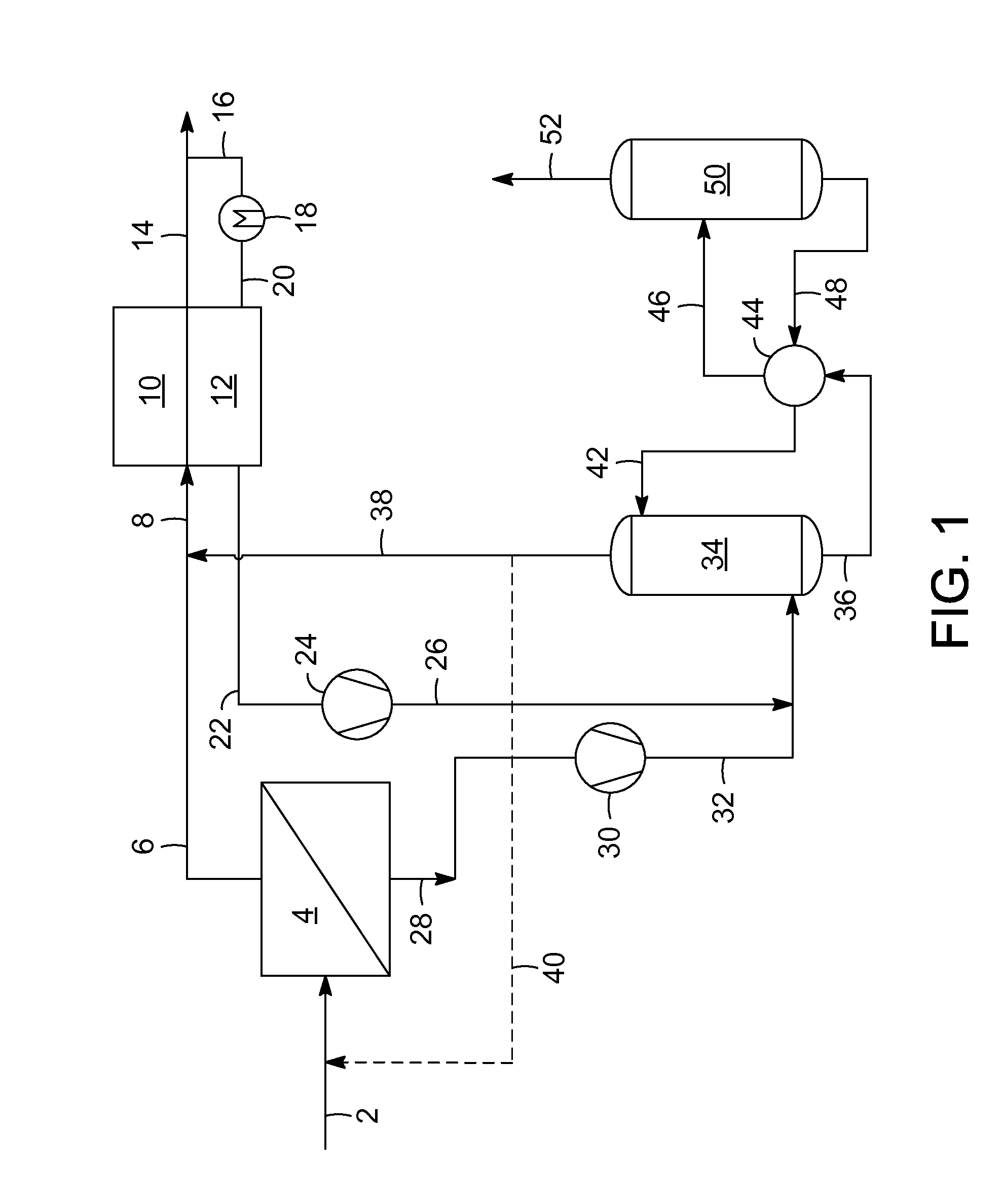
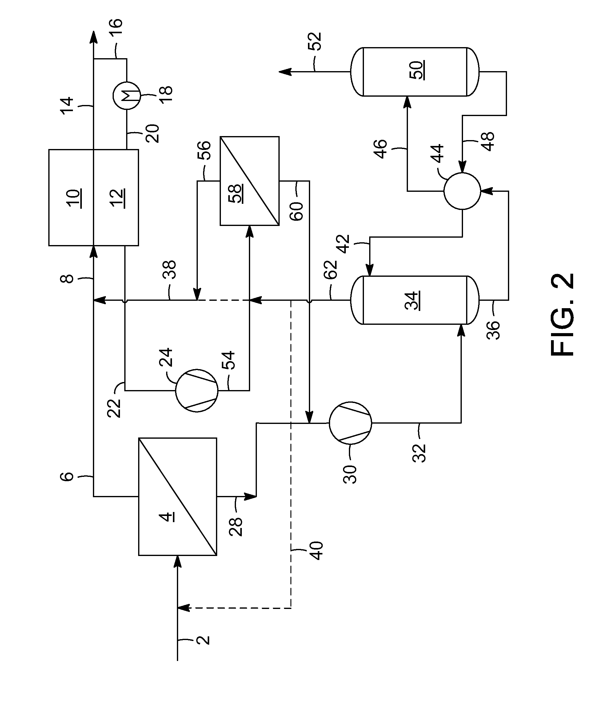
[0009]Ideally the treating process would be limited to the use of a combination of membranes and molecular sieve treaters to replace the amine columns that are frequently used for CO2 removal from natural gas. The motivation to eliminate the amine columns stems from the flow mal-distribution of the absorber / regenerator in the amine unit due to motion in a floating application. However, this process option inevitably produces a membrane permeate stream that has substantial amounts of hydrocarbon that would be wasted if not recovered. The process of the present invention places an amine column in a location so as to receive permeate gas from the membranes and / or regenerant gas from the molecular sieve column and to remove CO2 and other impurities from that gas to a level commensurate with re-introducing the product gas from the amine column back to either before the membrane unit or to a location immediately upstream of the molecular sieve treater. The latter location may be optimal i...


PUM

PropertyMeasurementUnit
concentrationaaaaaaaaaa
permeateaaaaaaaaaa
pressureaaaaaaaaaa

Abstract

The present invention provides a process for treating a natural gas stream comprising sending a natural gas stream to at least one membrane unit to produce a permeate stream containing a higher concentration of carbon dioxide and a retentate stream containing a lower concentration of carbon dioxide. Then the retentate stream is sent to an adsorbent bed to remove carbon dioxide and other impurities to produce a natural gas product stream. The regeneration gas stream is sent through the molecular sieve adsorbent bed to desorb the carbon dioxide. In one process flow scheme, the regeneration stream is combined with the permeate stream from the membrane unit. Then the combined stream is sent to an absorbent column to remove carbon dioxide from the permeate stream to produce a second natural gas product stream. In the alternative flow scheme, a second membrane unit is used to improve efficiency.

Description

CROSS-REFERENCE TO RELATED APPLICATION[0001]This application claims priority from Provisional Application No. 61 / 349,445 filed May 28, 2010, the contents of which are hereby incorporated by reference.BACKGROUND OF THE INVENTION[0002]This invention relates to a process for removing impurities from natural gas feeds. More particularly, this invention relates to a process for removal of impurities including carbon dioxide, hydrogen sulfide, water and mercury from natural gas in a floating environment, such as a ship, prior to liquefaction.[0003]A new type of vessel is being developed that may revolutionize offshore production of natural gas. The gas industry is currently planning to build a fleet of ships or barges that can be sailed or towed to the site of offshore gas deposits, extract the gas, pretreatment the natural gas to remove impurities, then liquefy it to become LNG and then offload the LNG to tankers for shipping to market. It is hoped that these floating liquefied natural g...

Claims


Application Information

Patent Timeline
Patent Type & Authority Applications(United States)
IPC IPC(8): B01D53/22
CPCB01D53/1443Y02C10/10B01D53/22B01D53/229B01D53/62B01D53/75B01D2252/20447B01D2252/20484B01D2252/20489B01D2253/108B01D2256/22B01D2256/245B01D2257/302B01D2257/304B01D2257/404B01D2257/504B01D2259/4566B01D2317/022C10L3/104Y02C10/04Y02C10/06Y02C10/08B01D53/1456Y02C20/40
Inventor DUNNE, STEPHEN R.DUNNE, PAMELA J.ZHOU, LUBOCOUGHLIN, PETER K.
Owner UOP LLC
Why Eureka
Try Eureka