
Method and system for generating spatially and temporally controllable concentration gradients

a technology of concentration gradient, which is applied in the field of method and system for generating spatial and temporal controllable concentration gradient, can solve the problems of unstable gradient, unstable gradient, and incompatibility of experiments with non-adherent and weakly adherent cells, and achieve the effect of regulating the cellular respons

Inactive Publication Date: 2011-12-08
THE BRIGHAM & WOMEN S HOSPITAL INC
View PDF3 Cites 10 Cited by
  • Summary
  • Abstract
  • Description
  • Claims
  • Application Information

AI Technical Summary

Benefits of technology

[0013]The present invention is directed methods and systems for rapidly generating concentration gradients of diffusible materials (including chemical compounds and biologic molecules), polymers, beads, particles and cells in the channel of a microfluidic device. In accordance with the invention, alternating flows are induced in the channel to produce multi-centimeter long concentration gradients. Methods and systems according to the invention use alternating flows and hydrodynamic stretching to rapidly generate long gradients of these gradient materials and long cross-gradients of two species of gradient materials in a simple microchannel. In accordance with the invention, the length of the concentration gradient can be predetermined for wide range of material properties. For example, a polyethylene-glycol) hydrogel gradient, a porous collagen gradient and a composite material with a hyaluronic acid / gelatin cross-gradient can be generated with continuous variations in material properties and in their ability to regulate cellular response. The present invention can be useful for creating anisotropic biomimetic materials and high-throughput platforms for investigating cell-microenvironment interaction.
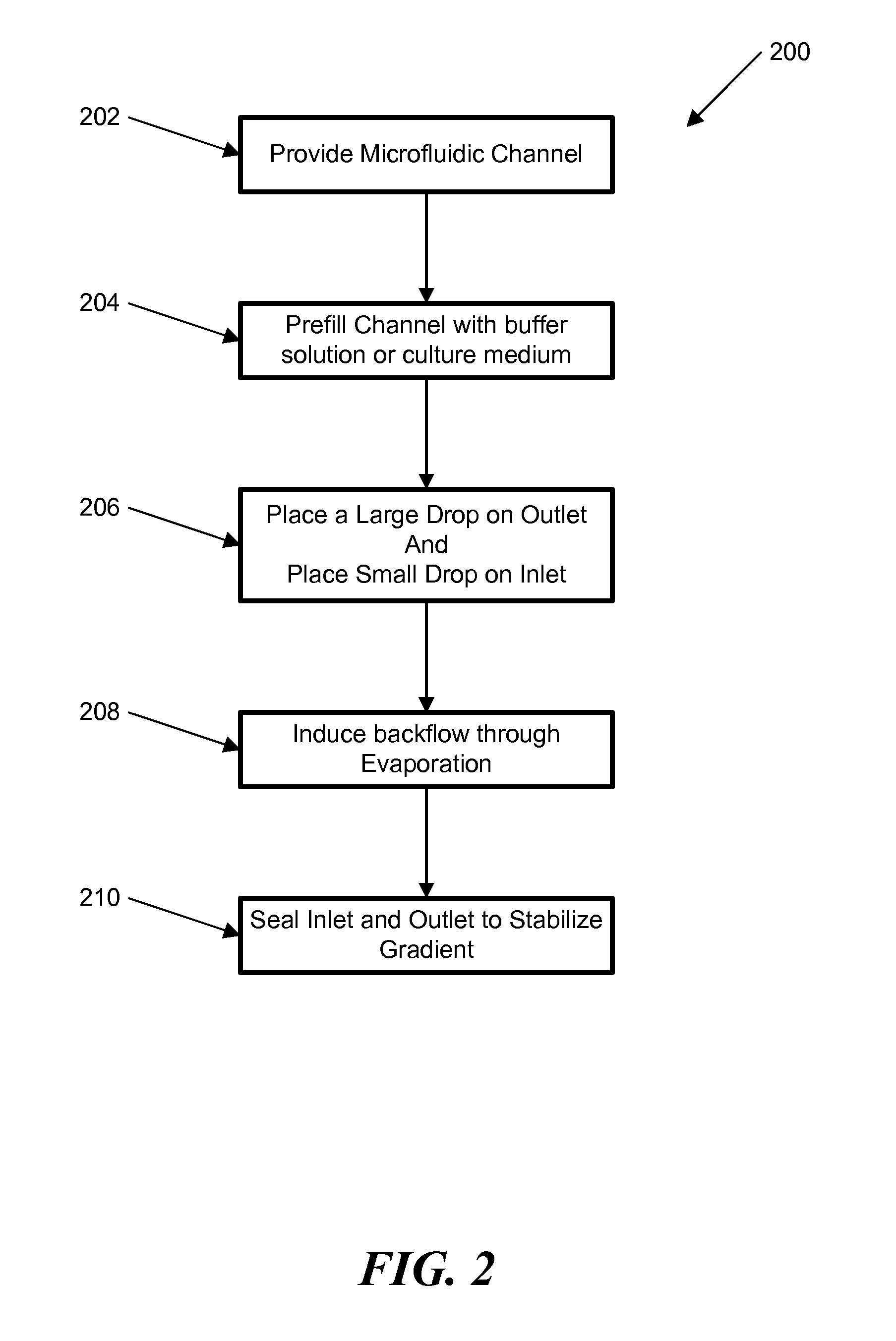
[0014]In one embodiment of the invention, methods and systems according to this embodiment utilize a forward flow induced by the passive-pumping and a reversed flow induced by evaporation to rapidly establish centimeter-length concentration gradients of molecules along the channel of a simple and portable microfluidic device. Passive-pumping is used to generate a forward flow from the inlet to the outlet of the channel, which introduced the gradient material (molecules of interest) into the microfluidic device in a rapid and simple manner and initiated a concentration gradient profile of the molecules due to the parabolic shape of the front flow. An evaporation-induced backward flow from the outlet to the inlet of the channel followed the forward flow resulting in the formation of dynamic concentration gradients of the molecule. The gradient profile can be stabilized by stopping the flow. The centimeter-length concentration gradients were in parallel with the flow direction along the microfluidic channel and can be spatially and temporally controlled.
[0017]The present invention provides methods and systems for simple and rapid generation of relatively long concentration gradients in portable microfluidic devices. The present invention can provide that: 1) the concentration gradient is generated by dispersion, the combined effect of convection and molecular diffusion, and flow reversal, which changes the direction of the parabolic flow; 2) due to the convection-driven nature, the process of gradient generation was rapid (within several minutes), highly dynamic (throughout the backward flow stage) and spatially / temporally controllable (by controlling the evaporation-induced backflow); 3) the gradient can be formed by consuming low amounts of the gradient material (particles, cells, or molecules, etc.) of interest; 4) centimeter-length concentration gradients can be generated parallel to the flow direction along the channel; and 5) the process is simple and highly reproducible in a portable microfluidic device, requiring only a pipette for implementation.
[0021]It is an object of the invention to rapidly generate a stable concentration gradient of a gradient material over a predefined length of a microfluidic channel.

Problems solved by technology

The ability to recreate the heterogeneity of the natural materials is a major challenge for investigating cell-material interactions and for developing biomimetic materials.
The first method is advantageous for producing stable complex gradients, but the experiments are not compatible with non-adherent and weakly adherent cells and the shear / drag force generated by the flow may alter the intercellular signaling pathways.
Moreover, to generate the laminar flows, pumping systems with external connections (i.e. tubing and valves) are often used, which limit the portability and ease of use of the device 16.
The second approach normally requires larger gradient generation times and the gradient produced is unstable and hard to maintain over long time periods.
Evaporation is a well-known issue when handling small liquid volumes, especially in microfluidic devices.
Diffusion-based approaches for gradient generation are limited to diffusible molecules and require long times to create millimeter length gradients, since the timescale for pure diffusion scales as length squared.
However, so far no generic platform employing dispersion to generate stable material gradients of single or multiple components over long distances have been developed.

Method used


Image

  • Method and system for generating spatially and temporally controllable concentration gradients
  • Method and system for generating spatially and temporally controllable concentration gradients
  • Method and system for generating spatially and temporally controllable concentration gradients

Examples


example 1

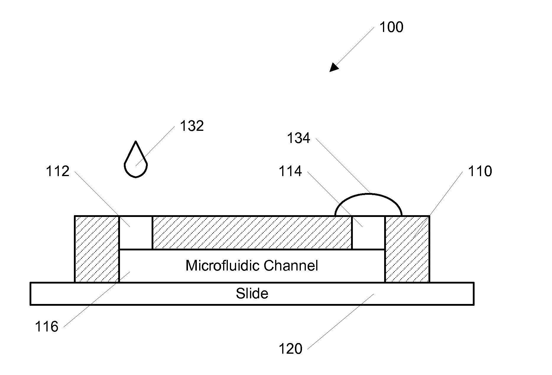
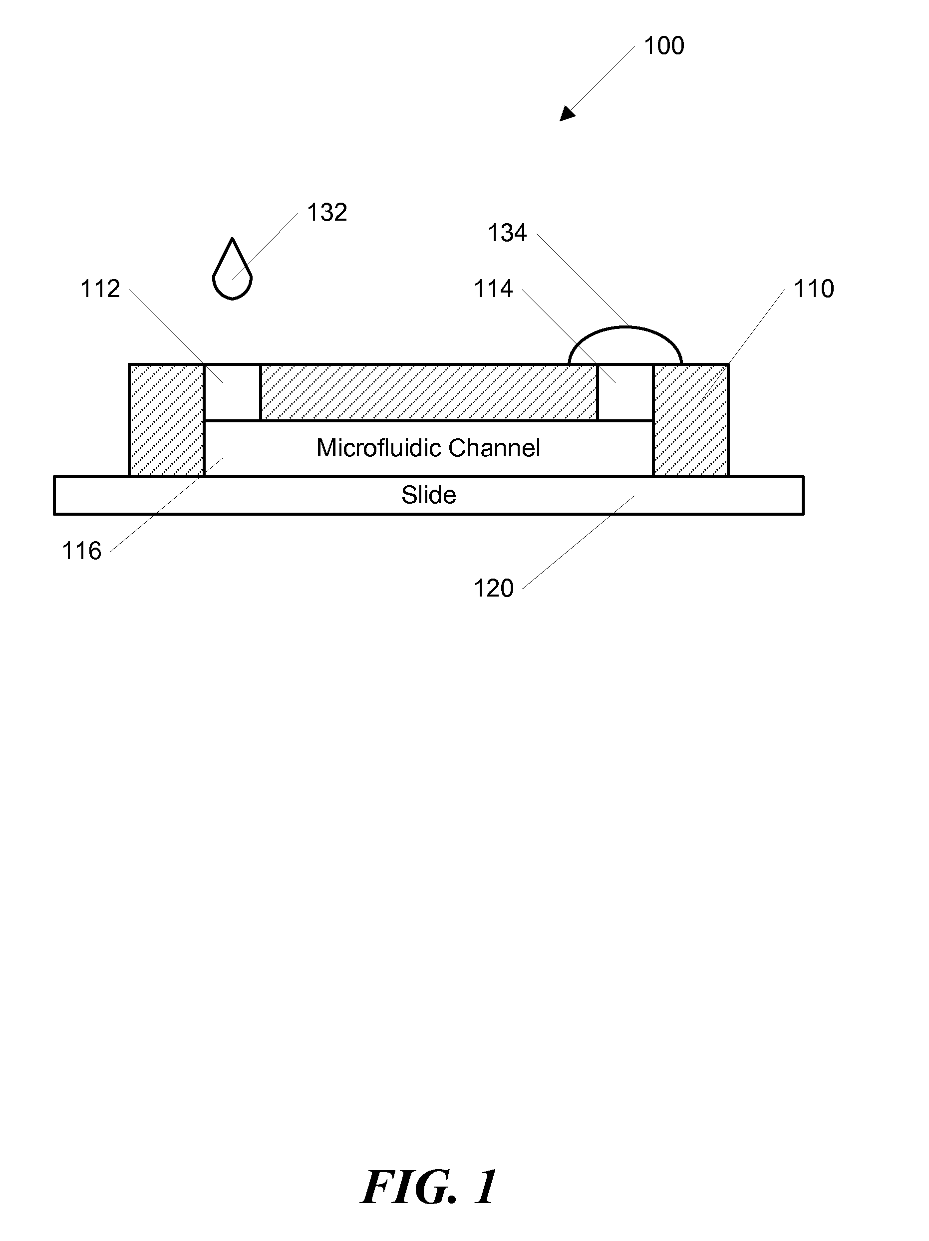
[0052]In one example according to the invention, the channel was initially filled with Dulbecco's Phosphate Buffered Saline (DPBS, Gibco, Carlsbad, Calif.). A 200 μL drop of DPBS was pipetted onto the outlet opening and a 2 μL drop of DPBS containing the molecule of interest was dropped onto the inlet opening and subsequently entered the channel automatically. After the small drop entered the channel completely, a second drop containing 2 μL was pipetted onto the inlet to continue the forward flow. When the inlet was not refilled, the forward flow would stop and a backflow occurred due to evaporation at the room humidity (˜65%). To visualize the dynamic process of the concentration gradient generation, fluorescein isothiocyanate-dextran (FITC-Dextran, molecular weight (MW): 10 kD) was used as the model molecule, and the fluorescence image series was captured using a Kodak Gel Logic 100 Imaging System, shown in FIGS. 4-6. The average fluorescence intensity along the whole channel was...

example 2

[0057]In another example, a stable concentration gradient was produced using the process shown in FIG. 3. As described above, FIG. 3 shows a schematic diagram of the gradient generation and stabilization process: A) Microfluidic channel was first filled with DPBS; a large drop of DPBS was placed on the outlet opening and a small drop of the gradient material containing diffusible molecules was pipetted on the inlet opening, B) solution was introduced into the channel automatically by the passive-pump-induced forward-flow; C) a concentration gradient of molecules was generated during the evaporation-based backward flow; D) the gradient profile could be stabilized by stopping the evaporation, either by sealing the inlet with mineral oil or by maintaining the microfluidic device at 100% humidity.

[0058]In this example, the microfluidic channel was initially filled with DPBS, and a 200 μL drop of DPBS was pipetted onto the outlet. A small drop of 2 μL DPBS containing FITC-Dextran was the...

example 3

Stabilized Concentration Gradient for Cytotoxicity Testing

[0064]In this example, the stabilized, spatially and temporally controllable concentration gradient technique is utilized for cytotoxicity testing. A cardiac muscle cell line (HL-1) is used to investigate the cytotoxicity of Alpha-cypermethrin, a cardiac toxin. Three drops of 2 μL medium containing 20 mM Alpha-cypermethrin were loaded consecutively into the micro-devices with HL-1 cells seeded along the channel. A concentration gradient of the toxin was established by evaporation when the micro device was left at ambient conditions for 5 min (5 min exposure does not cause severe damage to cell viability) and the gradient was stabilized when the micro device was transferred to the humidified incubator. HL-1 cells exposed to the toxin concentration gradient for 4 h exhibited distinguishable morphologies along the channel, with more severe effects observed in the regions containing higher concentrations of toxin. The drastic mor...


PUM


Abstract

The ability to rapidly generate concentration gradients of diffusible molecules has important applications in many chemical and biological studies. The present invention is directed to methods and systems for generating spatially and temporally controllable concentration gradients of molecules (i.e. proteins or toxins) in a portable microfluidic device. The formation of the concentration gradients can be initiated by an induced forward flow and further optimized during an induced backward flow. The forward and backward flows can be either passively induced and / or actively pumped. The centimeter-length gradients along the microfluidic channel can be spatially and temporally controlled by the backward flow. The gradient profile was stabilized by stopping the flow. In one example, a stabilized concentration gradient of a cardiac toxin, Alpha-cypermethrin, generated according to the invention was used to test the response of HL-1 cardiac cells in the microfluidic device, which correlated with toxicity data obtained from multi-well plates. The invention can be useful for bio-logical and chemical processes that require rapid generation of concentration gradients in a portable microfluidic device.

Description

CROSS-REFERENCE TO RELATED APPLICATIONS[0001]This application claims any and all benefits as provided by law of U.S. Provisional Application No. 61 / 114,539 filed Nov. 14, 2008, the entire contents of which are hereby incorporated by reference in its entirety.STATEMENT REGARDING FEDERALLY SPONSORED RESEARCH[0002]This invention was made with government support under Grant Nos. 103577, HL092836, DE019024, and EB007249 awarded by the National Institutes of Health. The US Government has certain rights in this invention.REFERENCE TO MICROFICHE APPENDIX[0003]Not ApplicableBACKGROUND[0004]1. Technical Field of the Invention[0005]The present invention is directed to methods and systems for rapidly generating concentration gradients of diffusible molecules, polymers, beads and cells. Further, the invention is directed to methods and systems for rapidly generating spatially and temporally controllable concentration gradients of these gradient materials in a portable microfluidic device.[0006]2...

Claims


Application Information

Patent Timeline
IPC IPC(8): G01N1/00C12Q1/02B01L3/00C12M1/34
CPCB01L3/50273B01L3/502776B01L2300/0816G01N1/405Y10T436/2575G01N2001/4088G01N2030/342G01N30/34G01N30/6095
Inventor KHADEMHOSSEINI, ALIDU, YANANHANCOCK, MATTHEW
Owner THE BRIGHAM & WOMEN S HOSPITAL INC
Learn More