The present invention is called an Intro-Angio-Guide because it combines in one device; (1) an
introducer sheath; (2) an angiographic catheter; and (3) a
guiding catheter for use with a
balloon angioplasty catheter, or a low profile
stent delivery system such as the stent-on-a-wire (S-O-A-W) stent
delivery system. Another way of looking at this device is that it combines, (1) an introducer sheath: and (2) an Angio-
Guide catheter which can serve as an angiographic catheter or as a
guiding catheter for a low profile stent
delivery system, and (3) a sheathing catheter that is soft and flexible enough in its
distal portion to allow it to be tracked over the shaft of a stent delivery system, such as S-O-A-W, to allow
backup and
low volume contrast injection in the more distal part of the coronary
artery during
stent placement. Thus, a single catheter (the Angio-
Guide catheter) can serve as both an angiographic catheter to perform angiography and as a guiding catheter when using the S-O-A-W or another small diameter delivery system for the stenting of a
blood vessel. The
advantage of the present invention compared to existing devices is that the introducer sheath fits snugly over the cylindrical shaft of the Angio-
Guide catheter and it has a wall thickness of less than 5 mils (a mil is 1 / 1,000 of an inch). It is practical to have a wall thickness for the introducer sheath of the Intro-Angio-Guide catheter that is only 2 to 3 mils. Because the thin-walled introducer sheath is inserted through the
groin when wrapped around the Angio-Guide catheter, it does not buckle as it would, at that very
thin wall thickness, if it weren't wrapped around a comparatively strong cylinder, namely, the shaft of the Angio-Guide catheter.
compared to existing devices is that the introducer sheath fits snugly over the cylindrical shaft of the Angio-Guide catheter and it has a wall thickness of less than 5 mils (a mil is 1 / 1,000 of an inch). It is practical to have a wall thickness for the introducer sheath of the Intro-Angio-Guide catheter that is only 2 to 3 mils. Because the thin-walled introducer sheath is inserted through the
groin when wrapped around the Angio-Guide catheter, it does not buckle as it would, at that very
thin wall thickness, if it weren't wrapped around a comparatively strong cylinder, namely, the shaft of the Angio-Guide catheter.
For
coronary angiography, the following procedure is used after a guide wire has been placed through the groin and advanced through the
femoral artery:1. The
dilator is inserted into the Intro-Angio-Guide catheter and the
dilator and the Angio-Guide are advanced over the guide wire, through the
skin and
soft tissue, and via the femoral (or other access
artery) to an area near the
target vessel to be studied or treated.2. After
insertion of the system, the
dilator and the guidewire are removed and the proximal end of the introducer sheath is secured to the
skin with a suture.3. The distal end of the Angio-Guide catheter is placed into the
ostium of the
target vessel (e.g.,
left coronary artery) where angiography is to be performed.4.
Contrast medium is injected at the proximal end of the Angio-Guide catheter and any stenosis is observed by x-
ray imaging.5. If no treatable stenosis is observed, the Intro-Angio-Guide is removed from the patient's body, but if a stenosis that requires
angioplasty or stenting is identified, then a S-O-A-W stenting system or other low profile
balloon angioplasty or stent system can be used to treat that stenosis, without requiring the exchange of the Intro-Angio-Guide to a new guiding catheter.
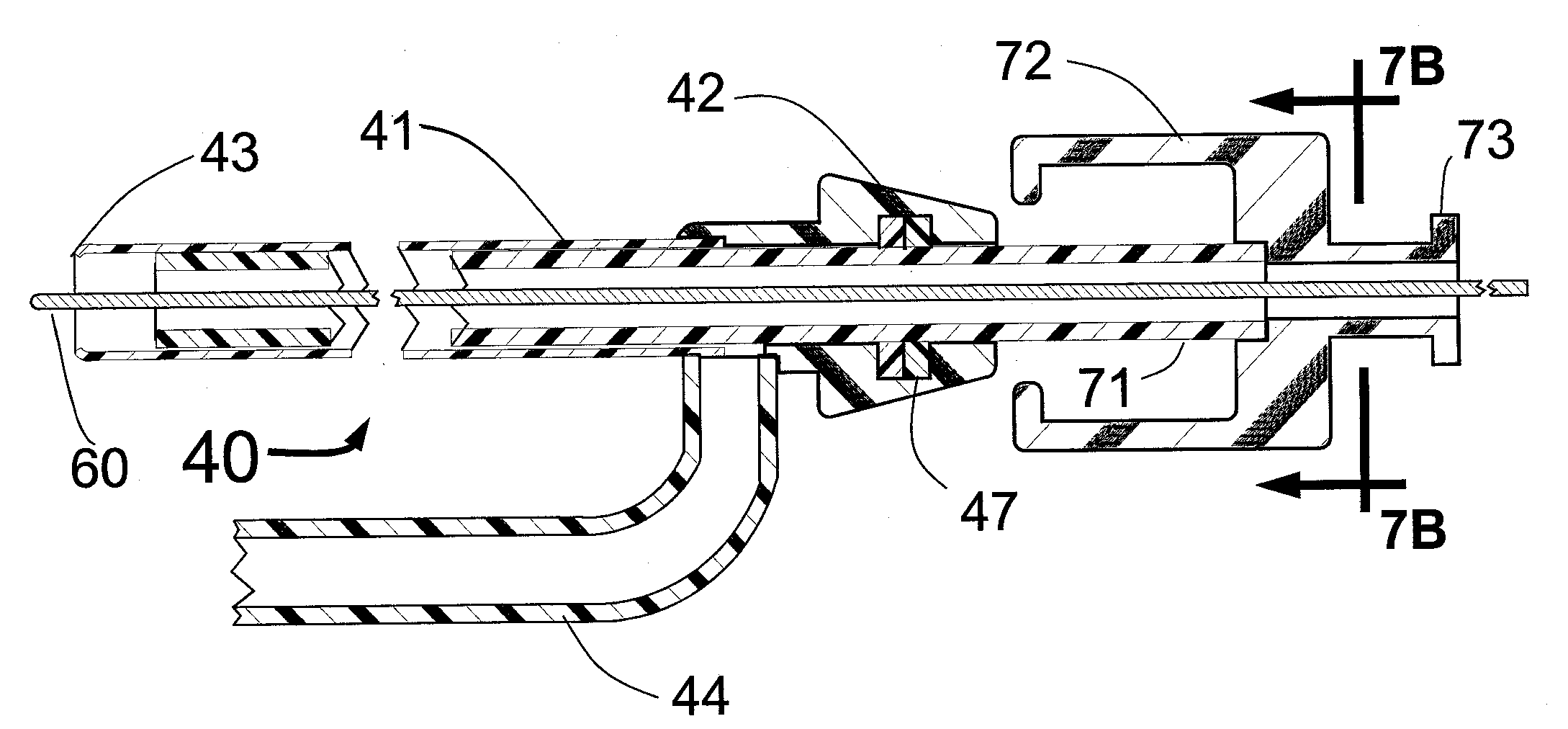
Because the introducer sheath fits snugly over the shaft of the Angio-Guide catheter with a clearance of only 1 to 2 mils, and because it has such a thin wall, the outside diameter of the Intro-Angio-Guide catheter will only be about 0.6 FR larger than the outside diameter of the Angio-Guide catheter. This compares with a diameter increase of about 2.0 FR when a conventional introducer sheath is used. This smaller outer diameter for the Intro-Angio-Guide system will tend to reduce the risk of bleeding at the groin that can be a serious problem for patients undergoing angiography or stenting. To facilitate the thinnest wall introducer sheath component with the maximum wall strength, a flat wire
helix or
braid may be included within the plastic of the present invention Intro-Angio-Guide introducer sheath. It is also envisioned that the distal end of the sheath, the distal end of the Angio-Guide catheter and the distal end of the straightening dilator used with the Angio-Guide catheter would have radiopaque markers to facilitate delivery under
fluoroscopy. It is also envisioned that the distal 10-20 cm of the Angio-Guide will be relatively soft and flexible to allow it to be tracked down a coronary artery over the shaft of a
balloon angioplasty catheter or a stent delivery system, and thus act as a distal support catheter, providing for superb “
backup” to allow better steering and
lesion crossing of the stent system as well as imaging of distal target lesions using a minimum of contrast.
The inventive means and method described herein is particularly valuable for the new type of stent delivery system (the S-O-A-W system) that is described in U.S. Pat. No. 6,375,660. The very small stent delivery system outside diameter made possible by the S-O-A-W system can allow, for the first time, the use of the same diameter introducer sheath and guiding catheter both for angiography and for stenting. Specifically, a 4 FR, 4.5 FR or 5 FR Intro-Angio-Guide catheter can be used to first perform angiography. If stenting of a stenosis is then required, the S-O-A-W stent delivery system can accomplish the stenting procedure using the same Intro-Angio-Guide system as was used for angiography. If a conventional stent delivery catheter is used to deliver a conventional stent, this would often require an introducer sheath and a guiding catheter with a larger diameter as compared to the Intro-Angio-Guide. It is anticipated that a unique Intro-Angio-Guide catheter whose size is 4.5±0.3 FR would be ideal for first performing angiography and then stenting any stenosis that is found in any artery of the body.
Thus one object of the present invention is to use the Intro-Angio-Guide catheter for angiography, thus minimizing the opening through the patient's
skin.

