Method for Removing CO2 from Coal-Fired Power Plant Flue Gas Using Ammonia as the Scrubbing Solution, with a Chemical Additive for Reducing NH3 Losses, Coupled with a Membrane for Concentrating the CO2 Stream to the Gas Stripper

a technology of flue gas and ammonia, which is applied in the field of apparatus and methods for removing and capturing carbon dioxide from flue gas stream, can solve the problems of high cost of electricity, and high energy requirements for co2/sub

Active Publication Date: 2011-12-22
UNIV OF KENTUCKY RES FOUND
View PDF11 Cites 19 Cited by
  • Summary
  • Abstract
  • Description
  • Claims
  • Application Information

AI Technical Summary

Benefits of technology

[0008]In accordance with the purposes of the present invention as described herein, a method is provided for removing and capturing carbon dioxide from a fluid stream such as a flue gas stream. The method comprises the steps of (a) exposing the fluid stream to an aqueous scrubbing solution that removes and holds carbon dioxide from the fluid stream, (b) pa

Problems solved by technology
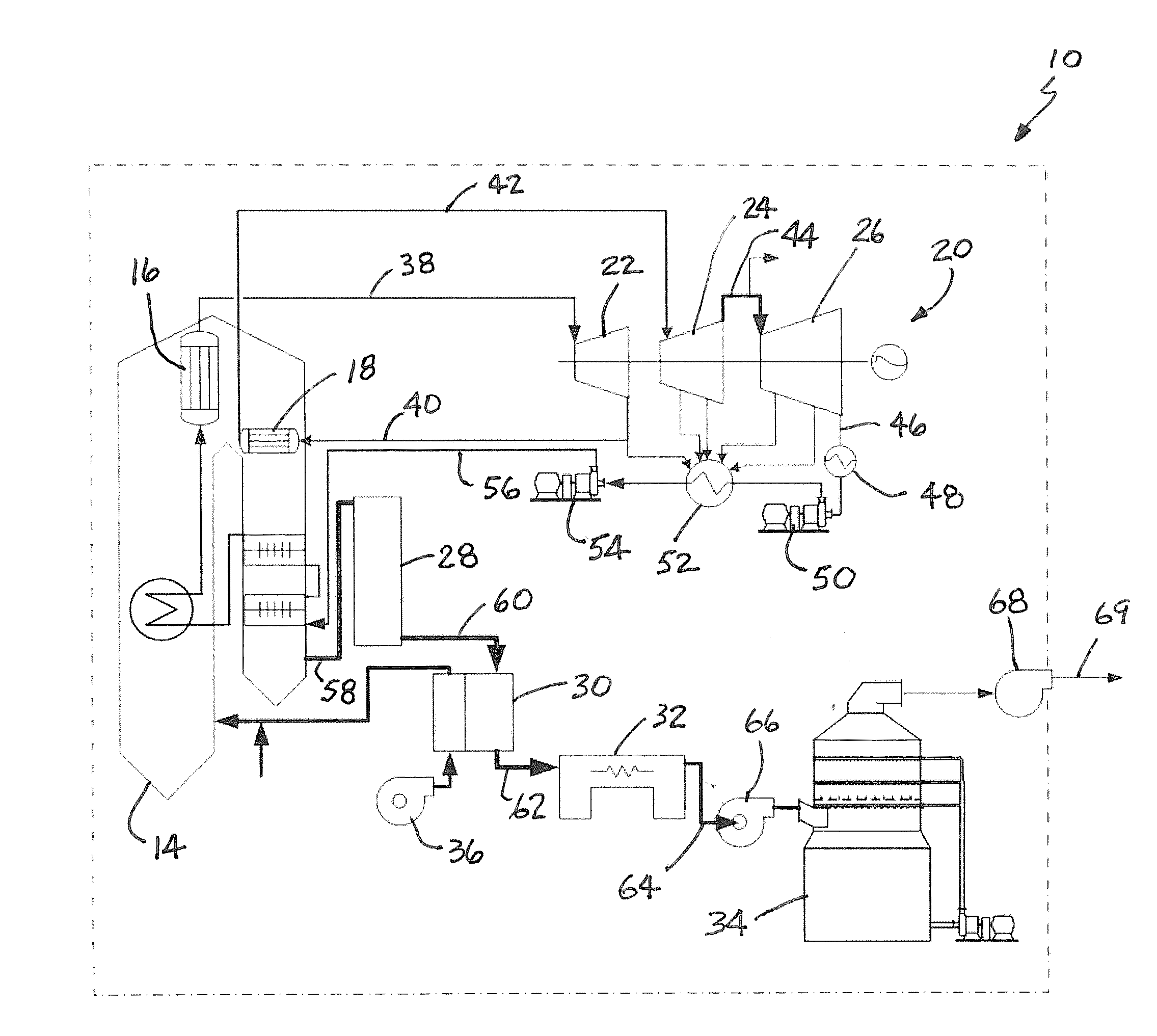
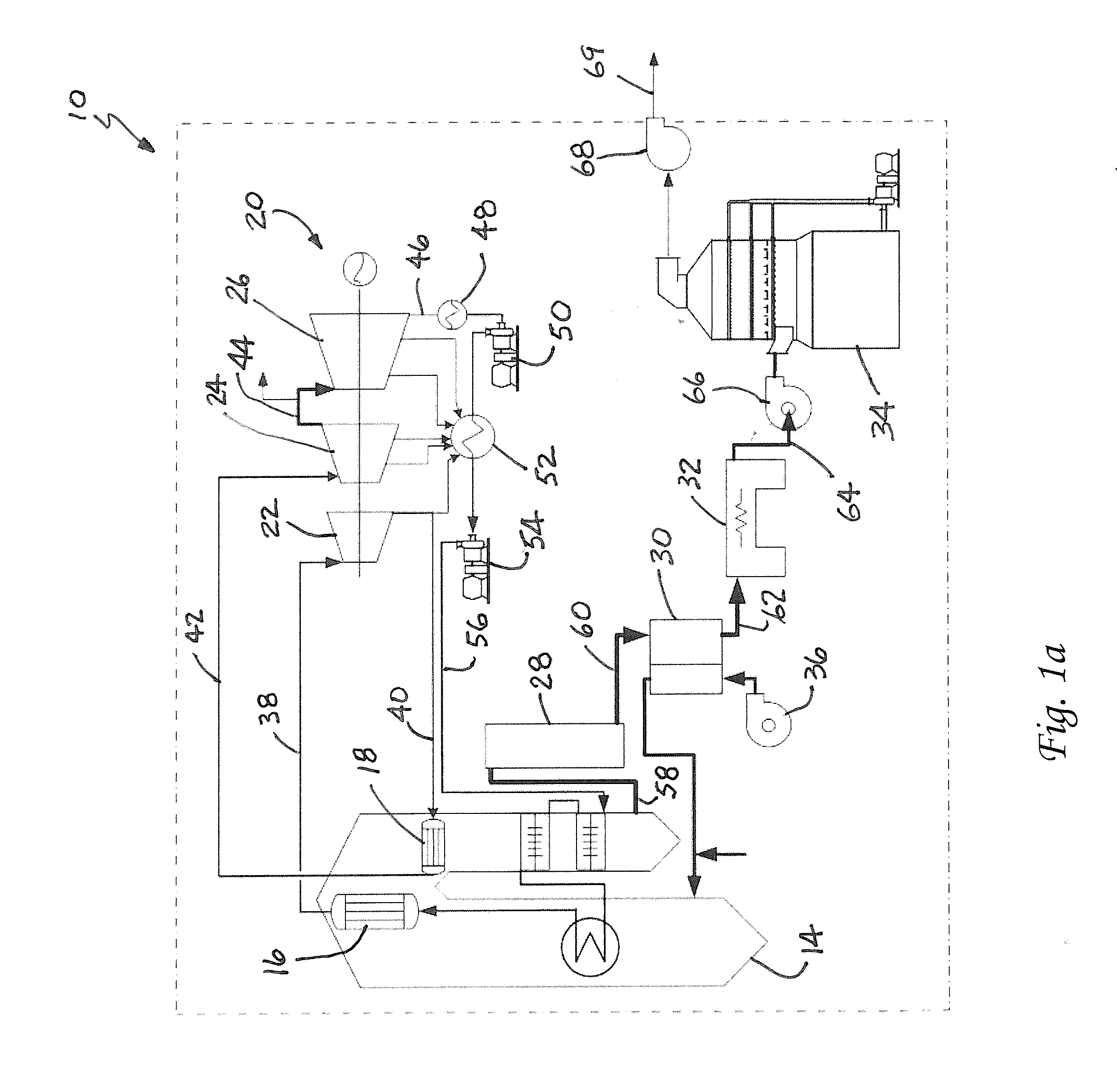
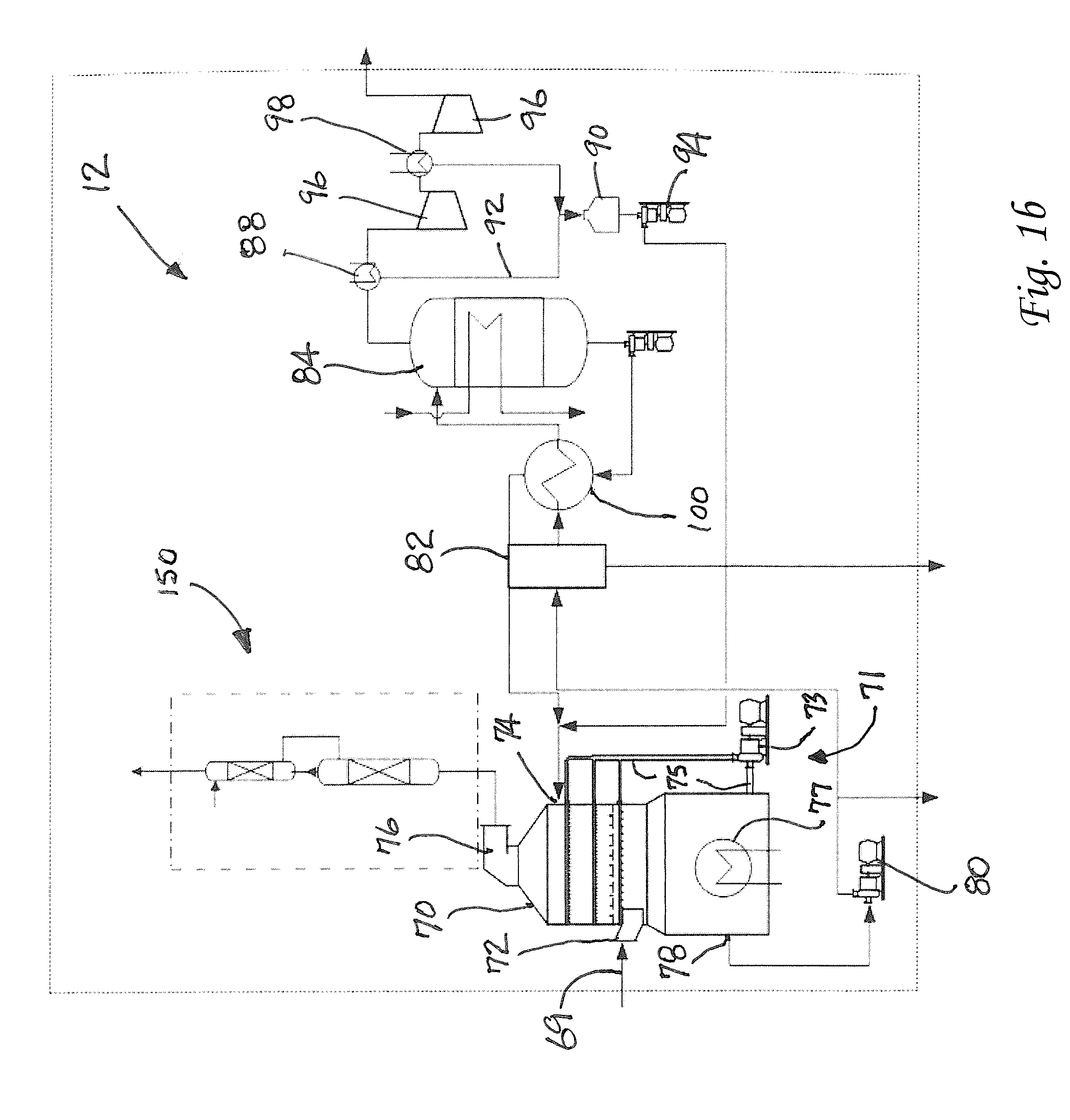
While absorption/stripping with amine-based scrubber systems has been successfully used for natural-gas purification, it poses several technical challenges, including the fact that flue gas from utility boilers is at atmospheric pressure and the concentration of CO2 in the flue gas is relatively low at 12-14%.
Another technical hurdle is the energy requirements for the CO2 capture/desorption devices to regenerate absorber reagents.
First

Method used


Image

  • Method for Removing CO2 from Coal-Fired Power Plant Flue Gas Using Ammonia as the Scrubbing Solution, with a Chemical Additive for Reducing NH3 Losses, Coupled with a Membrane for Concentrating the CO2 Stream to the Gas Stripper
  • Method for Removing CO2 from Coal-Fired Power Plant Flue Gas Using Ammonia as the Scrubbing Solution, with a Chemical Additive for Reducing NH3 Losses, Coupled with a Membrane for Concentrating the CO2 Stream to the Gas Stripper
  • Method for Removing CO2 from Coal-Fired Power Plant Flue Gas Using Ammonia as the Scrubbing Solution, with a Chemical Additive for Reducing NH3 Losses, Coupled with a Membrane for Concentrating the CO2 Stream to the Gas Stripper

Examples


example 1

[0033]FAU zeolite membranes were hydrothermally grown onto tubular mullite supports (so far in our lab, 1.2 cm diameter and 10-cm-ong from Masuda Corporation, the diameter and length could be varied for commercial application), yielding membranes with a total surface area of 37.68 cm2 (will depend on the dimension of support selected). Before synthesis, the outer surface of the mullite tube was seeded with a water slurry of commercially available NaY crystal seeds. The seeded support was then air dried at 80° C. for several hours. The desired gel composition was optimized to grow an FAU zeolite membrane layer onto the mullite support mentioned above. The FAU-type (Y-type herein) zeolite membrane was crystallized from a reactive gel mixture with the following molar composition: SiO2: 0.04 Al2O3: 0.7 Na2O: 0.1 (TMA)2O: 31.5 H2O where TMA+ refers to tetramethylammonium cation. A typical synthesis procedure for FAU membranes followed: NaOH pellets (99.2 wt %, Fisher) were weighted and d...

example 2

[0035]Ammonia loss during CO, absorption experiments were conducted in a 1 inch ID scrubber packed with Berl ceramic saddles. Simulated flue gas consisting of 14 vol % CO2, balance air, was continuously fed into the scrubber bottom with counter-current liquid flow. Experiments were conducted under liquid to gas ratio (L / G) of 100 at ambient pressure and temperature of 20° C. A 2 L volume of solution was loaded with CO2 in a step fashion with the volume passed through the column into a second reservoir. After each step a solution sample was retrieved and analyzed for ammonia loss. CO2 loading was continued until the difference in inlet and outlet CO2 gas concentration was minimal.

[0036]Nickel chloride (Fisher, purity:>97%) with ammonia to metal mole ratio 20:1 was added to 12 wt % aqueous ammonium solution and compared to a control solution without additive. Ammonia contents were determined using Dionex ICS-3000 ion chromatograph. Compared to control, the nickel containing ammonia so...

example 3

[0037]Using the supported membranes described in Example 1 the membrane performance was evaluated. The evaluation apparatus was operated in a counter-current configuration with a tubular zeolite membrane sealed in a stainless steel membrane cell with Viton O-rings. A 15 ml / min constant flow dual piston pump delivered the feed solution to the membrane cell at a maximum pressure of 6.9 MPa. The feed solutions were fed from a magnetically stirred 1.5 l reservoir. Feed solution temperature in the membrane cell was controlled at a constant temperature by an adjustable heating tape. The back-pressure regulator installed at the channel outlet allowed fine control over a wide range of applied pressures within the membrane unit. A thermocouple was inserted into the cell shell side in order to accurately monitor the feed solution temperature in the membrane cell. The NF / RO experiments were run under constant operating conditions until a satisfactory steady state was reached. In the duration o...


PUM

PropertyMeasurementUnit
Weightaaaaaaaaaa
Weightaaaaaaaaaa
Percent by massaaaaaaaaaa

Abstract

A method for removing and capturing carbon dioxide from a fluid stream includes the steps of exposing the fluid stream to an aqueous scrubbing solution that removes and holds carbon dioxide from the fluid stream, passing the aqueous scrubbing solution through a membrane in order to separate excess water from the scrubbing solution and increase the concentration of carbon dioxide in the scrubbing solution, heating the scrubbing solution having an increased concentration of carbon dioxide so as to release carbon dioxide gas and recycling the scrubbing solution. A carbon dioxide capture apparatus includes a carbon dioxide scrubber, a membrane downstream from the scrubber for separating water and concentrating carbon dioxide in a scrubbing solution and a stripper vessel.

Description

TECHNICAL FIELD AND INDUSTRIAL APPLICABILITY OF THE INVENTION[0001]The present invention relates generally to the separation of carbon dioxide from a fluid or process stream and, more particularly, to an apparatus and method for removing and capturing carbon dioxide from a flue gas stream.BACKGROUND OF THE INVENTION[0002]At present, the energy sector is responsible for about three-fourths of the anthropogenic carbon dioxide emissions. Over the past 15 years, economic activity in the U.S. has increased by about 50%; total U.S. electricity demand has increased 30% over the same period. In the coming years, the surge in the U.S. demand for electric power shows no signs of abating. Economic activity in the U.S. is projected to expand 49% by 2020. Accordingly, in the same period, the demand for electricity is projected to increase by another 30%. With this increase in electricity demand, CO2 emissions from more and more power plants will become an even greater driving force in rising atm...

Claims


Application Information

Patent Timeline
IPC IPC(8): C01B31/20B01D50/00C01B32/50
CPCB01D53/1425B01D2325/36B01D67/0051B01D69/04B01D71/028B01D2252/102B01D2258/0283B01D2311/04B01D2311/08B01D2311/2626F23J15/04F23J2215/50F23J2219/40Y02C10/06B01D53/1475Y02C20/40Y02E20/32B01D71/0281
Inventor LIU, KUNLEINEATHERY, JAMES K.REMIAS, JOSEPH E.LI, XIANSEN
Owner UNIV OF KENTUCKY RES FOUND
Why Eureka
Try Eureka