Method and apparatus for the energy densification of a material in the form of divided solids, with a view to obtaining pyrolysis oils for energy purposes

a technology of energy densification and divided solids, which is applied in the field of heat treatment divided solids, can solve the problems of unsuitable devices for treating, unsuitable pyrolysis biomass, and poor operating yield of known pyrolysis treatments, and achieves high process yields

Active Publication Date: 2012-02-23
LEPEZ CONSEILS FINANCE INNOVATIONS LCFI +1
View PDF5 Cites 32 Cited by
  • Summary
  • Abstract
  • Description
  • Claims
  • Application Information

AI Technical Summary

Benefits of technology

[0011]An object of the invention is to propose a method and an installation for energy densification of a material in the form of divided solids, in particular a biomass, in order to obtain pyrolytic oils for energy purposes, while avoiding the above-mentioned drawbacks, i.e. a method and an installation capable simultaneously of implementing operating condit

Problems solved by technology

Nevertheless, devices of those types are not suitable for treating at temperatures lying in the range 300° C. to 850° C. as is required in the field of pyrolysis where it is desired to maximize the gas phase content and thereby optimize the yield of energy densification.
Under all circumstances, known pyrolysis treatments continue to have a poor operating yield, and in particular they are unsuitable for pyrolyzing a biomass in order to obtain pyrolytic oils for energy purposes.
Such an installation is of no advantage in the context of an application to energy densification of biomass in order to obtain pyrolytic oils for energy purposes because of the poor yield of the resulting oils, which yield may at best reach about 400 oil.
Furthermore, the electrical power is u

Method used


Image

  • Method and apparatus for the energy densification of a material in the form of divided solids, with a view to obtaining pyrolysis oils for energy purposes
  • Method and apparatus for the energy densification of a material in the form of divided solids, with a view to obtaining pyrolysis oils for energy purposes
  • Method and apparatus for the energy densification of a material in the form of divided solids, with a view to obtaining pyrolysis oils for energy purposes

Examples


Embodiment Construction

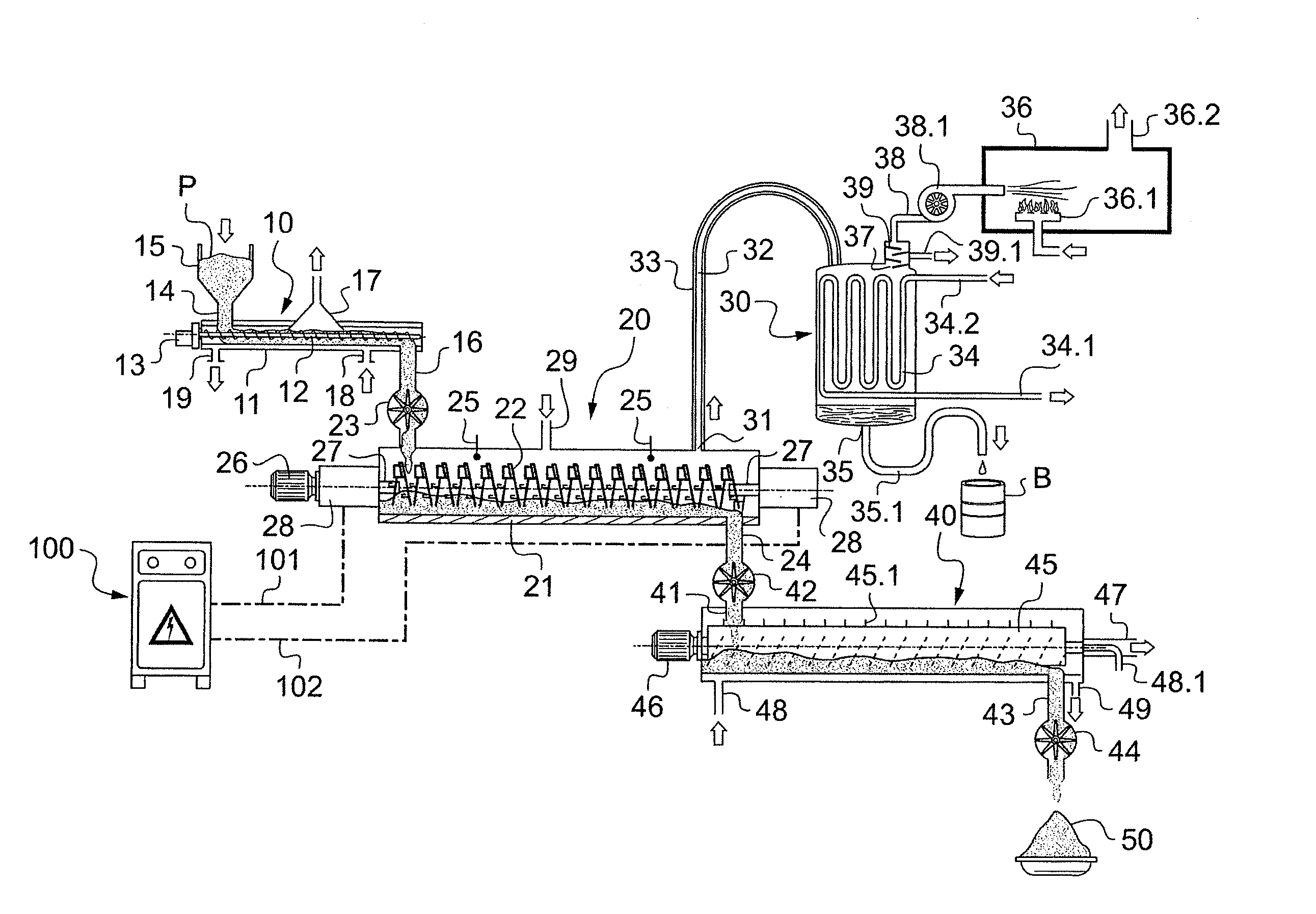
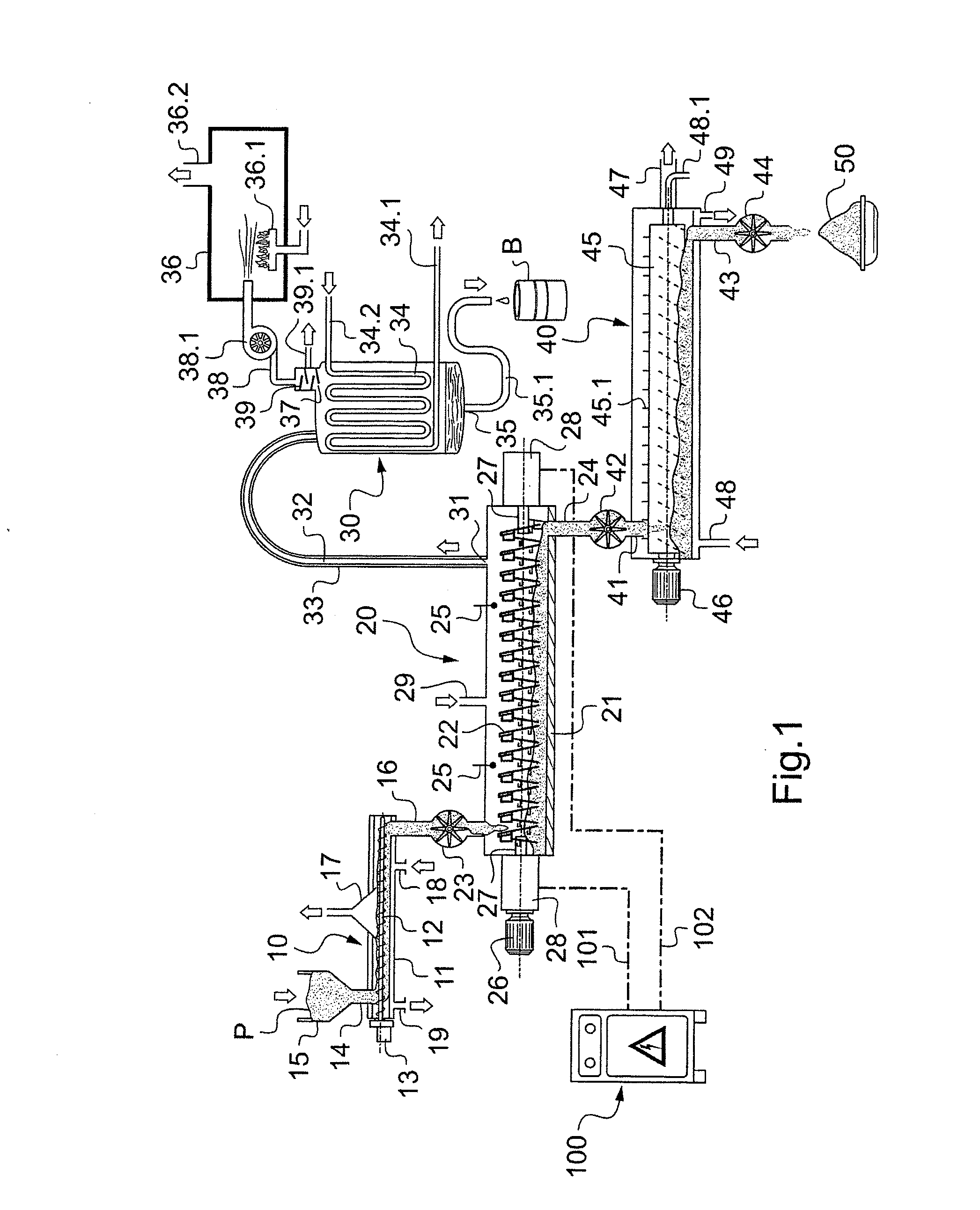
[0040]FIG. 1 is a diagram of an installation (1) for treating a material in divided solid form, in particular a biomass, with energy densification of the material in order to obtain pyrolytic oils for energy purposes.

[0041]The material in question is generally a biomass, where this term covers the biodegradable fractions of materials, wastes, and residues coming from agriculture, forestry, and related industries, and in particular biomasses of vegetable origin or solid fractions of sludge from waste water treatment, and biodegradable fractions of industrial and municipal waste. Nevertheless, the invention may be applied to treating other industrial waste that does not come within the above definition of biomass, for example polymer waste (plastics materials, rubbers, . . . ).

[0042]In general, the materials in question are divided solids that are capable of producing pyrolytic oils when they are raised to temperatures in the range 300° C. to 800° C. in the absence of oxygen, said oil...


PUM


Abstract

A method and installation for energy densification of a material to obtain pyrolytic oils for energy. The method includes preconditioning the material by heating and drying to raise the material temperature close to 100° C. and a relative humidity not exceeding about 10%; pyrolyzing the material that is subsequently caused to flow through a substantially hermetic reactor containing at least one transfer screw or vibrating tube heated by the Joule effect, the material heated progressively in the range of 300° C. to 850° C., the electrical power passing through the transfer screw or the vibrating tube for providing heating regulated as a function of the material in order to obtain the desired temperature level during the transit time of the material through the reactor; extracting pyrolysis gas from a high portion of the reactor for rapid recondensation in a vertical condenser; and recovering pyrolytic oils from a low portion of the vertical condenser.

Description

[0001]The present invention relates to energy densification of a material in divided form, in particular a biomass, in order to obtain pyrolytic oils for energy purposes.[0002]In terms of biomasses, they may be biomasses of vegetable origin or solid particles from waste water treatment sludges. They may equally well be industrial waste, in particular polymer waste (plastics materials, rubbers, etc.).BACKGROUND OF THE INVENTION[0003]Devices are known for heat treating divided solids, which devices comprise at least one transfer member having at least a longitudinal axis and a helical portion mounted to rotate about said longitudinal axis inside a tubular casing, the helical portion being made of an electrically conductive material and being connected to a source of electrical power so as to constitute heating transfer means. One such device is disclosed in documents WO-A-99 / 39549 and FR-A-2 892 888 in the name of the Applicant.[0004]As variants, treatment devices are also known that ...

Claims


Application Information

Patent Timeline
IPC IPC(8): C10B19/00C10B7/10
CPCC10B7/10Y02E50/14C10C5/00C10B53/02Y02E50/10
Inventor LEPEZ, OLIVIERSAJET, PHILIPPE
Owner LEPEZ CONSEILS FINANCE INNOVATIONS LCFI
Why Eureka
Try Eureka