Semiconductor device manufacturing method

a manufacturing method and semiconductor technology, applied in semiconductor devices, capacitors, electrical devices, etc., can solve the problems of significant reduction of hole size, difficult to form hole patterns solely with photolithography, and difficult to form hole patterns only with photolithography, so as to ensure the opening ability of the etching process, prevent misalignment in this direction, and ensure the effect of sufficient photolithographic resolution margin

Active Publication Date: 2012-03-22
LONGITUDE LICENSING LTD
View PDF3 Cites 3 Cited by
  • Summary
  • Abstract
  • Description
  • Claims
  • Application Information

AI Technical Summary

Benefits of technology

[0009]According to the method disclosed in Patent Document 1 described above, the amount of etching of the SiN protecting film covering the surface of the wiring layer is decreased during the etching for the formation of contacts for connecting between capacitors and underlying nodes. However, as the miniaturization progresses, the diameter of the storage nodes is reduced and the depth thereof is increased further. Thus, according to this method in which the etching for the formation of capacitors and the etching for the formation of contacts for connecting the capacitors to underlying nodes are performed simultaneously, the aspect ratio during the etching is increased significantly, which makes the etching itself difficult. Moreover, it also becomes difficult to achieve alignment and dimensional control for avoiding short circuit with other nodes or misalignment relative to the underlying connection nodes, causing hampering on miniaturization of memory cells.
[0014]In exemplary embodiments, a pattern used to etch the first interlayer insulation film for formation of contact holes and via holes for accommodating conductive plugs is a slit pattern extending in an orthogonal direction to the wiring layer. Therefore, the misalignment in this direction is prevented. Further, since the pattern is a line pattern, a sufficient photolithographic resolution margin can be ensured easily for miniaturization of the semiconductor device, and the opening ability for the etching process also can be ensured easily. Further, during the slit etching and the CMP for isolation of contacts, the insulation protecting films of the wiring lines are protected by the dummy insulation films formed above the wiring lines in the same layout as the wiring layer. Therefore, the reduction of thickness of the insulation protecting films can be prevented during these processes. This makes it possible to ensure a sufficient processing margin when the dimensions of and intervals between the wiring lines and the conductive plugs are reduced, and makes it easy to miniaturize the internal structure of the semiconductor device.

Problems solved by technology

Recent progress in miniaturization of semiconductor devices has made it difficult to form hole patterns solely with photolithography.
Therefore, the hole size is reduced significantly, which makes it difficult to form the hole pattern only with photolithography.
This makes it difficult to leave the SiN film with a sufficient thickness so as not to expose the wiring layer ultimately.
If the initial thickness of the SiN film is increased to ensure the SiN film is left with a sufficient thickness, it becomes difficult to fill the narrow spaces between the wiring layers arranged with a minimum pitch, with the insulation film.
This poses a problem that the increased thickness of the SiN film for protecting the wiring lines hampers the miniaturization of the semiconductor device.
Thus, according to this method in which the etching for the formation of capacitors and the etching for the formation of contacts for connecting the capacitors to underlying nodes are performed simultaneously, the aspect ratio during the etching is increased significantly, which makes the etching itself difficult.
Moreover, it also becomes difficult to achieve alignment and dimensional control for avoiding short circuit with other nodes or misalignment relative to the underlying connection nodes, causing hampering on miniaturization of memory cells.

Method used


Image

  • Semiconductor device manufacturing method
  • Semiconductor device manufacturing method
  • Semiconductor device manufacturing method

Examples


first embodiment

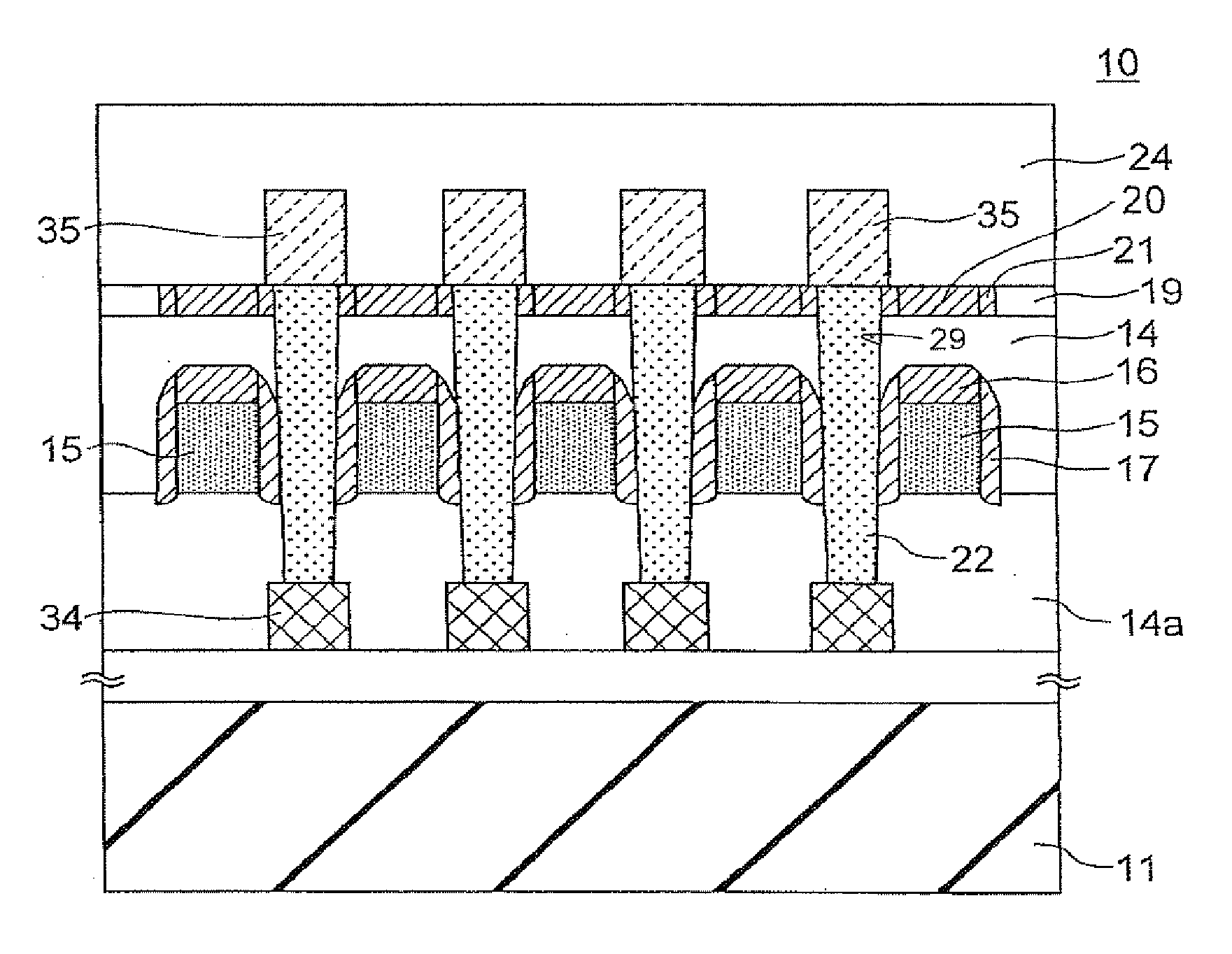
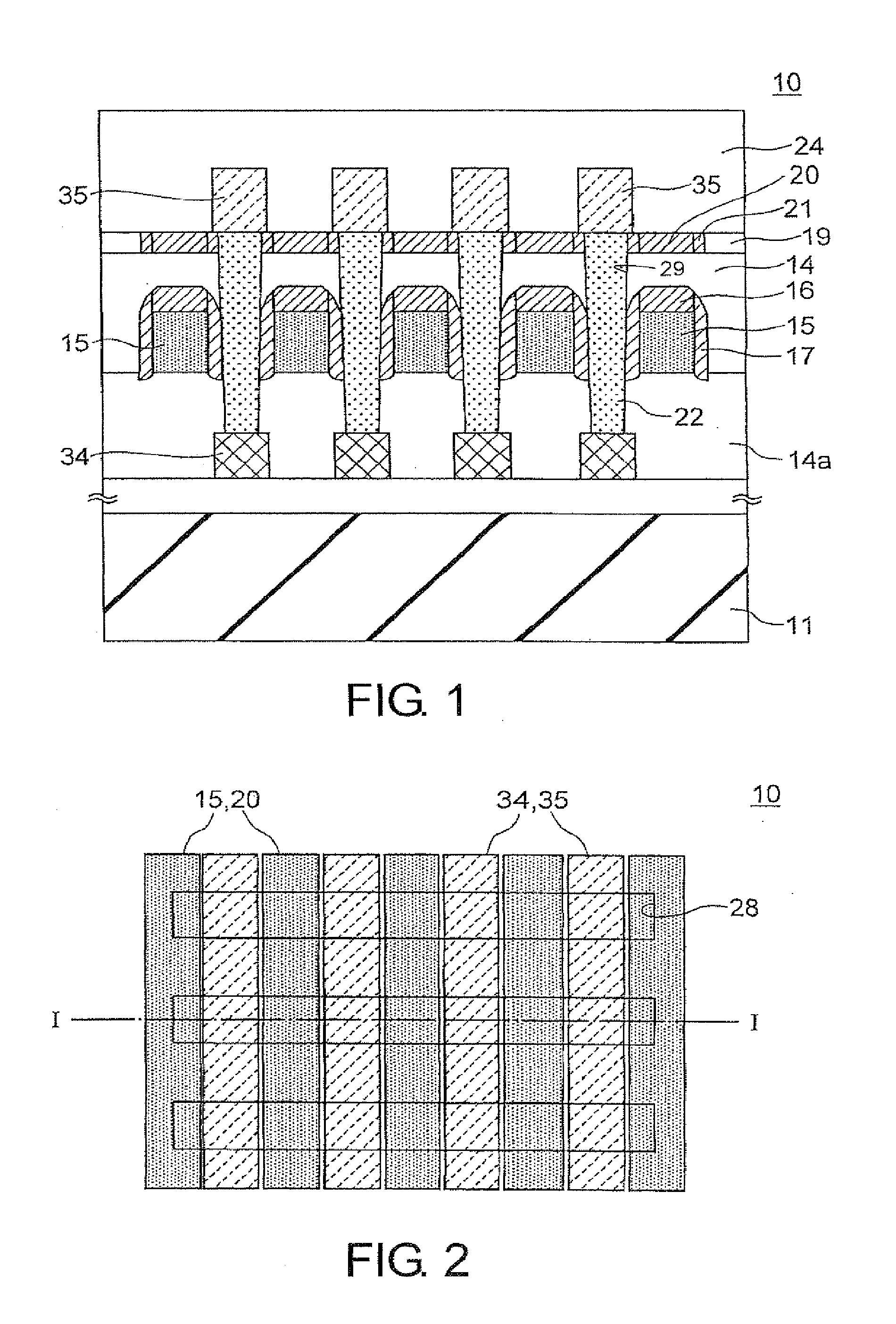
[0028]FIG. 1 is a cross-sectional view showing a semiconductor device according to this invention. FIG. 2 shows a pattern layout of this semiconductor device. FIG. 1 is a cross-sectional view taken along the line I-I of FIG. 2.

[0029]As shown in FIGS. 1 and 2, a semiconductor device 10 has a semiconductor substrate 11, first to third wiring layers 34, 15 and 35 formed on top of the semiconductor substrate 11, first to fourth interlayer insulation films 14a, 14, 19, and 24 for insulating between these wiring layers, dummy mask layers 20 and 21 interposed between the second interlayer insulation film 14 and the fourth interlayer insulation film 24 and formed above wiring lines of the second wiring layer 15, and via plugs 22 for connecting the first wiring layer 34 and the third wiring layer 35. Each of the via plugs 22 passes through between two adjacent wiring lines of the second wiring layer 15.

[0030]Each of the wiring lines of the second wiring layer 15 is provided with a silicon ni...

third embodiment

[0046]FIG. 9 is a cross-sectional view showing a semiconductor device according to a third exemplary embodiment of this invention. Like FIG. 2 and so on, FIG. 10 shows a layout pattern of the semiconductor device of this FIG. 9 is a cross-sectional view taken along the line IX-IX of FIG. 10.

[0047]The semiconductor device according to the third embodiment relates to a case in which the configuration of this invention is applied to a logic circuit. In the logic circuit, a first wiring layers 31, a second wiring layer 15 and a third wiring layer 32 are illustrated. These wiring layers may be formed of a material such as tungsten, aluminum, or copper. The semiconductor device 10B is manufactured by a process as described below. Firstly, element isolation regions 12 are formed to define active regions on a semiconductor substrate 11 by a STI process used in a conventional manufacturing process of semiconductor devices. Then, a MISFET (not shown) having a source / drain diffusion layer and...

fourth embodiment

[0057]The input / output device 150 may be a display device such as a liquid crystal display. The storage device 140 other than the semiconductor storage device may be a hard disk or an MO drive. However, this invention is not limited to these. The input / output device 150 may be either one of input and output devices. The semiconductor storage device 120 is for example a RAM (Random Access Memory) or a ROM (Read Only Memory), and is more specifically, a DRAM such as a SRAM (Static Random-Access-Memory), a SDRAM (Synchronous Dynamic Random-Access-Memory), a DDR-SDRAM (Double Data Rate Synchronous Dynamic Random-Access-Memory), a DDR2-SDRAM (Double Data Rate 2 Synchronous Dynamic Random-Access-Memory), or a DDR3-SDRAM (Double Data Rate 3 Synchronous Dynamic Random-Access-Memory), or a storage medium formed by a semiconductor element such as a flash memory. Although only one each of the components of the system is shown in FIG. 11 for the sake of simplification, the numbers of the compon...


PUM


Abstract

A miniaturized semiconductor device is provided by reducing the design thickness of a wiring line protecting film covering the surface of a wiring layer, and reducing the distance between the wiring layer and via plugs formed by a self-aligning process. Dummy mask layers extending in the same layout pattern as the wiring layer is formed above the wiring layer covered with a protecting film composed of a cap layer and side wall layers. In the self-aligning process for forming via plugs in a self-aligned manner with the wiring layer and its protecting film, the thickness of the cap layer is reduced and the design interval between the via plugs is reduced, whereby the miniaturization of the semiconductor device is achieved.

Description

CROSS REFERENCE TO RELATED APPLICATIONS[0001]This application is a division of co-pending application Ser. No. 12 / 420,307 filed on Apr. 8, 2009, which claims foreign priority to Japanese patent application No. 2008-103284 filed on Apr. 11, 2008. The entire content of each of these applications is hereby expressly incorporated by reference.BACKGROUND OF THE INVENTION[0002]1. Field of the Invention[0003]This invention relates to a semiconductor device, a manufacturing method thereof, and a data processing system. More particularly, this invention relates to a semiconductor device having wiring lines the surfaces of which are covered with a protecting insulation film, a manufacturing method thereof, and a data processing system including such a semiconductor device.[0004]2. Description of the Related Art[0005]Recent progress in miniaturization of semiconductor devices has made it difficult to form hole patterns solely with photolithography. In cell arrays of a memory product such as a ...

Claims


Application Information

Patent Timeline
Patent Type & Authority Applications(United States)
IPC IPC(8): H01L21/768
CPCH01L21/76831H01L28/91H01L27/10855H01L21/76897H10B12/0335
Inventor KOBAYASHI, HIROTAKA
Owner LONGITUDE LICENSING LTD
Why Eureka
Try Eureka