Microbial Electrolytic Cell

a technology of electrolysis cell and microorganism, applied in cell components, electrochemical generators, enzymology, etc., can solve the problems of increasing the ohmic loss of electrical potential undesired, reducing the cce to 6-33%, and generally not being practicable in field applications

Inactive Publication Date: 2012-04-05
ARIZONA STATE UNIVERSITY
View PDF3 Cites 9 Cited by
  • Summary
  • Abstract
  • Description
  • Claims
  • Application Information

AI Technical Summary

Benefits of technology

[0022]It is an advantage of the present invention that the MECs may be prepared without the need for metal catalysts. However, in certain embodiments, it may be desirable to include such catalysts, and, therefore the invention contemplates that in certain embodiments, the MECs may be formed where the cathode electrode further comprises a metal catalyst. Exemplary such metal catalysts may be selected from the group consisting of cobalt, copper, iron, lead, nickel, palladium, tin, tungsten, platinum group metals, or an alloy comprising one of more of the group.
[0023]In each of the aspects of the invention described herein, the microbial electrolytic cell of the invention may independently further comprise one or more of: 1) a pump to circulate the fluid within the reservoir; 2) a pH measurement device configured to measure the pH of the fluid contained within the reservoir; 3) a gas flow meter configured to measure an amount of H2 gas produced by the microbial electrolytic cell; 4) a potentiostat configured to apply a voltage between 0.2 volts and 1.2 volts between the anode and the cathode, and 5) a reference electrode electrically coupled to an electrical circuit comprising the cathode and the anode; including combinations of the aforementioned and all five of the aforementioned components.
[0024]In specific embodiments, the organic donor material for each of the aspects described

Problems solved by technology

However, H2 loss by diffusion into an anode chamber was large in some cases (Rozendal et al., 2008), decreasing CCE down to 6-33%.
Although H2 oxidation by ARB might not be a significant H2 loss in a single-chamber MEC, since current produced by H2 oxidation produces H2 gas on the cathode again; it increases ohmic losses of electrical potential which is undesired.
Using inhibitors is generally not practical for field applications, due

Method used


Image

  • Microbial Electrolytic Cell
  • Microbial Electrolytic Cell
  • Microbial Electrolytic Cell

Examples


example one

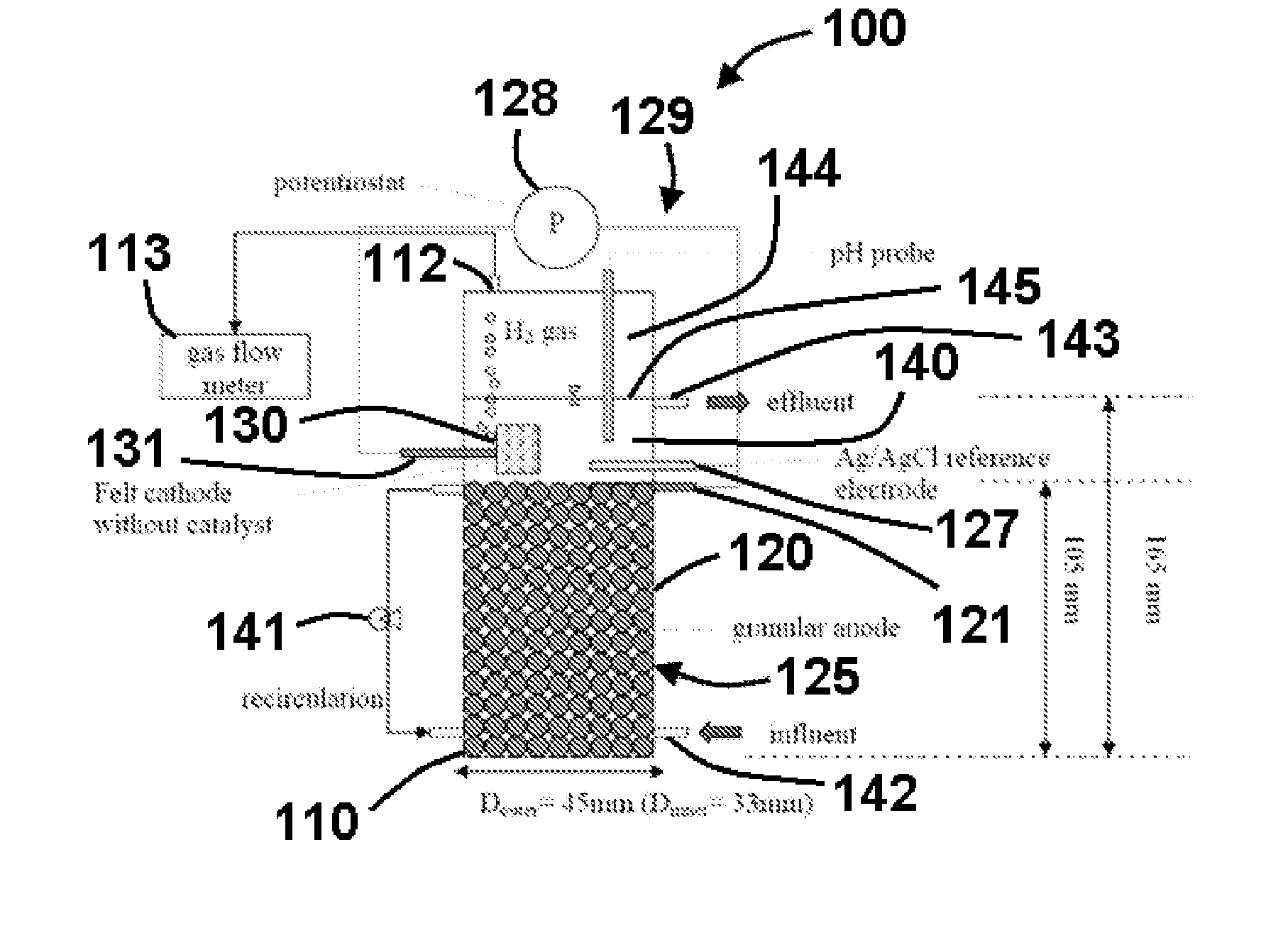
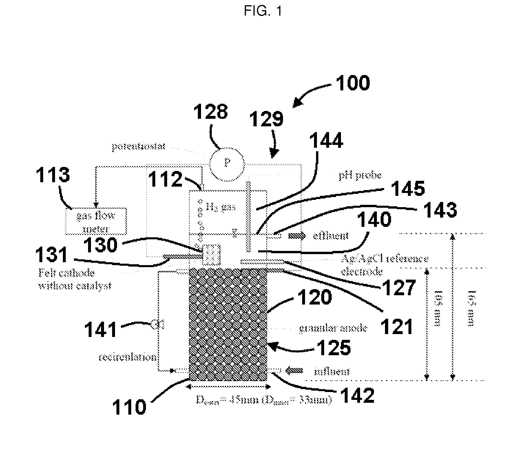
[0078]In a specific exemplary embodiment, an MEC comprised a glass cylinder with a diameter of 4.5 cm and height of 21.6 cm. Graphite rods (OD 0.8 cm, McMaster-Carr, USA) were cut into 2-3-cm long pieces and packed in the single cell up to a height of 10.5 cm to form the anode bed. The total volume of the single MEC was 161 mL, the empty-bed working volume was 140 mL, the effective working volume was 122 mL (excluding electrode volume), and gas headspace was 21 mL. The reported volumetric current density or volumetric H2 production rate is based on the empty-bed working volume of 140 mL. The average specific surface area of the granular anode was 4.15 m2 / m3 of the empty-bedworking volume. Carbon felt (#43199, Alfa Aesar, MA, USA) without a chemical catalyst was used as the cathode, and its geometric surface area was 21.8 cm2.

[0079]To connect the electrodes, graphite rods (OD 0.4 cm and length 5.4 cm) were inserted into the top areas of the granule anode, and the cathode felt was pen...

example two

[0089]In the present example it is demonstrated that a large geometric surface area formed by the use of many individual graphite fibers packed or bundled into a fiber bundle provides a high H2 production rate in the MEC. The large geometric surface area produces a high ratio of ARB-biofilm density to MEC system volume. The electrode surface area must be large enough for ARB biofilm to form (at least larger than 1-2 μm), and electrode must have a surface areas as large as possible per reactor volumes, since the ARB biofilm is the catalysts for acetate oxidation on electrode.

[0090]FIG. 4 illustrates the upflow-type single-chamber MEC that was used to test the use of graphite small-fiber bundles as anodes for MECs. The total volume of the MEC was 145 mL, and the working volume was 125 mL. The volumetric current density or volumetric H2 production rate is reported herein based on the working volume of 125 mL. Three bundles of the graphite fiber were used as the anode and one bundle was...


PUM


Abstract

System and methods for efficiently capturing hydrogen gas from a microbial electrolytic cell. Certain aspects of the invention describe microbial electrolytic cells in which the cathode is located above the anode and proximal to a fluid level and a gas headspace in the single-chamber microbial electrolytic cell. In other aspects, the invention relates to improved and high volumetric production rate of hydrogen gas effected by increasing the geometric surface area of the electrodes. Combinations of these aspects also are contemplated.

Description

RELATED APPLICATIONS[0001][Not Applicable]FEDERALLY SPONSORED RESEARCH OR DEVELOPMENT[0002][Not Applicable]BACKGROUND OF THE INVENTION[0003]A. Field of the Invention[0004]Embodiments of the present invention relate generally to a system and method for efficiently capturing hydrogen gas from a microbial electrolytic cell (MEC). In particular, embodiments of the present invention concern the systems and methods where the cathode is located above the anode and proximal to a fluid level and a gas headspace in a single-chamber microbial electrolytic cell. In other embodiments, the MEC is formed using graphite small fiber bundles to decrease reactor volume and thereby increase the volumetric H2 rate of the MEC.[0005]B. Description of Related Art[0006]There is an ever-increasing demand for energy conversion devices that may be used to produce electricity using non-fossil fuel technologies. In this regard, renewable fuels are employed in microbial fuel cells to generate Hydrogen (H2).[0007]...

Claims


Application Information

Patent Timeline
IPC IPC(8): H01M8/16C25B1/02
CPCC12N13/00C12P3/00H01M4/8626H01M4/90H01M4/92Y02E60/56H01M8/04082H01M8/16H01M2250/40Y02E60/527H01M8/0234Y02E60/50
Inventor RITTMANN, BRUCE E.LEE, HYUNG-SOOLTORRES, CESAR I.
Owner ARIZONA STATE UNIVERSITY
Why Eureka
Try Eureka