Fluorescence analyzing apparatus and fluorescence detecting apparatus

a fluorescence detecting and fluorescent image technology, applied in the field of light analyzing apparatus, can solve the problems of expensive camera having a pixel count of several hundred times the number of captured dna fragment molecules, and achieve the effects of low cost, efficient detection, and preventing one fluorescent image from overlapping

Active Publication Date: 2012-04-26
HITACHI HIGH-TECH CORP
View PDF7 Cites 30 Cited by
  • Summary
  • Abstract
  • Description
  • Claims
  • Application Information

AI Technical Summary

Benefits of technology

[0019]According to the present invention, when a fluorescent image of a sample on a substrate is measured, the fluorescence intensities of a plurality of fluorescent materials can be calculated using a smaller number of detectors than the number of types of the fluorescent materials, whereas the same number of detectors as the number of types thereof has conventionally been required, so that efficient detection can be achieved. In particular, three, four, or more types of fluorescent materials can be identified by one detector, and the fluorescence intensities thereof can be measured, so that a system can be constructed comprehensively at low cost.
[0020]In addition, in the case of the dispersive method using a prism or diffraction grating, it is necessary to detect dispersed fluorescence by means of a large number of pixels. Further, in order to prevent one fluorescent image from overlapping with another fluorescent image adjacent thereto, it is necessary to secure a sufficiently large pixel count within a detector, for detecting fluorescence from one capture region. In contrast, according to the present invention, such dispersion is not necessary, and an influence of overlapping with adjacent another portion is small. Accordingly, an interval between regions in which oligonucleotides and the like are captured can be reduced, and fluorescence from a larger number of samples can be analyzed at the same time. The use of such a high-density substrate can lead to enhancement in sample analysis throughput as well as a more simplified system.
[0021]In addition, for example, in the case where the number of regions in which oligonucleotides to be measured are captured is the same, efficient detection can be achieved using a smaller pixel count, so that the cost of a two-dimensional sensor can be reduced. In addition, because the optical resolution can be made equivalent to an interval between the regions in which the oligonucleotides are captured, an inexpensive lens can be used instead of a light collecting lens having a large numerical aperture, and an immersion lens does not need to be used, so that the operability can be enhanced.

Problems solved by technology

Note that, according to this technique, because the sample DNA fragment molecules to be analyzed are randomly captured on the substrate surface, an expensive camera having a pixel count of several hundred times the number of the captured DNA fragment molecules is necessary.

Method used


Image

  • Fluorescence analyzing apparatus and fluorescence detecting apparatus
  • Fluorescence analyzing apparatus and fluorescence detecting apparatus
  • Fluorescence analyzing apparatus and fluorescence detecting apparatus

Examples


embodiment 1

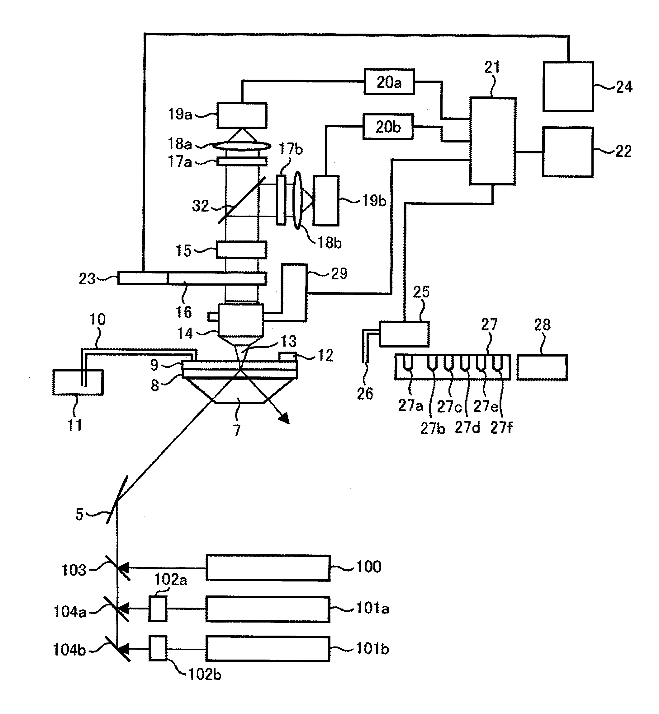
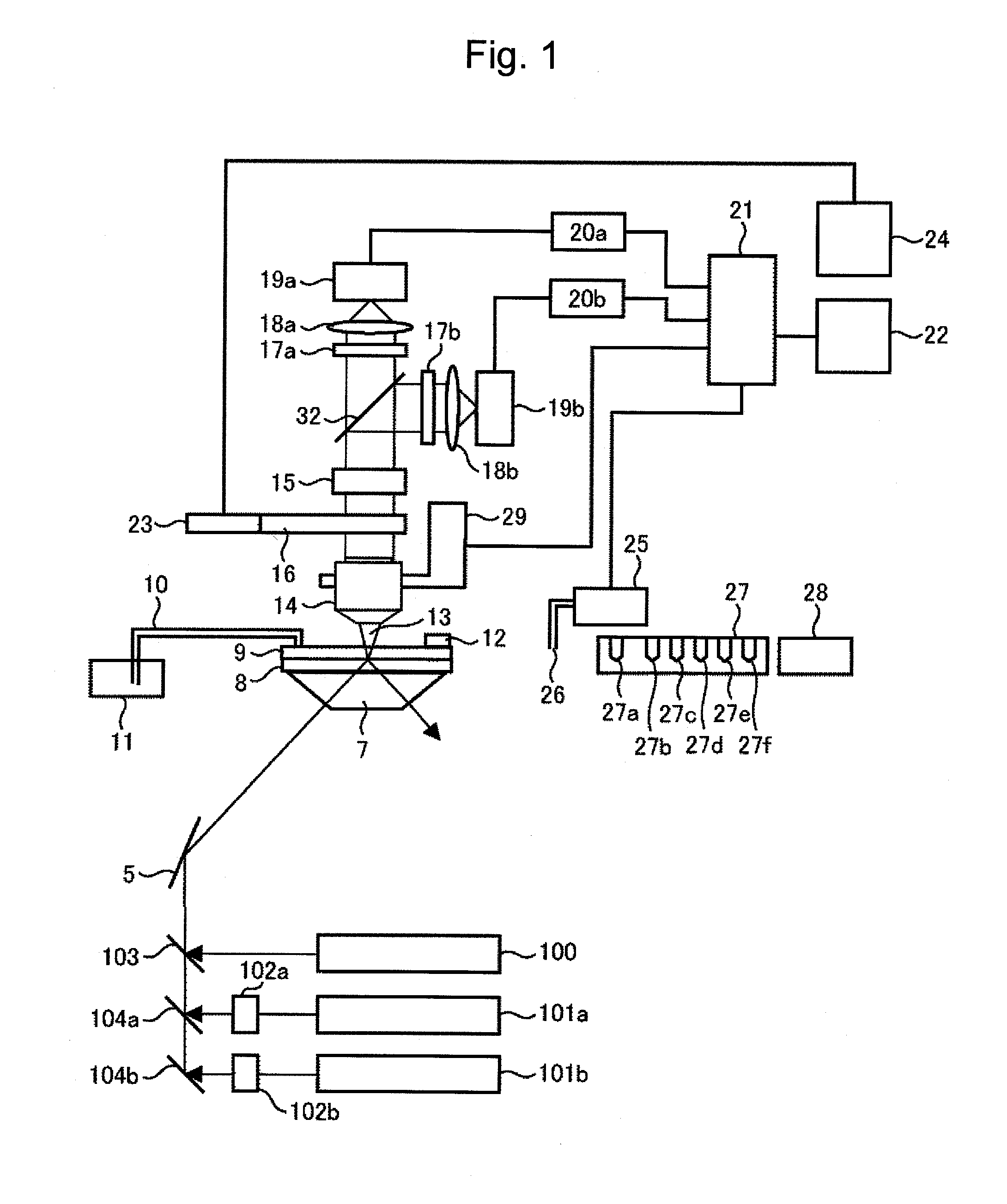
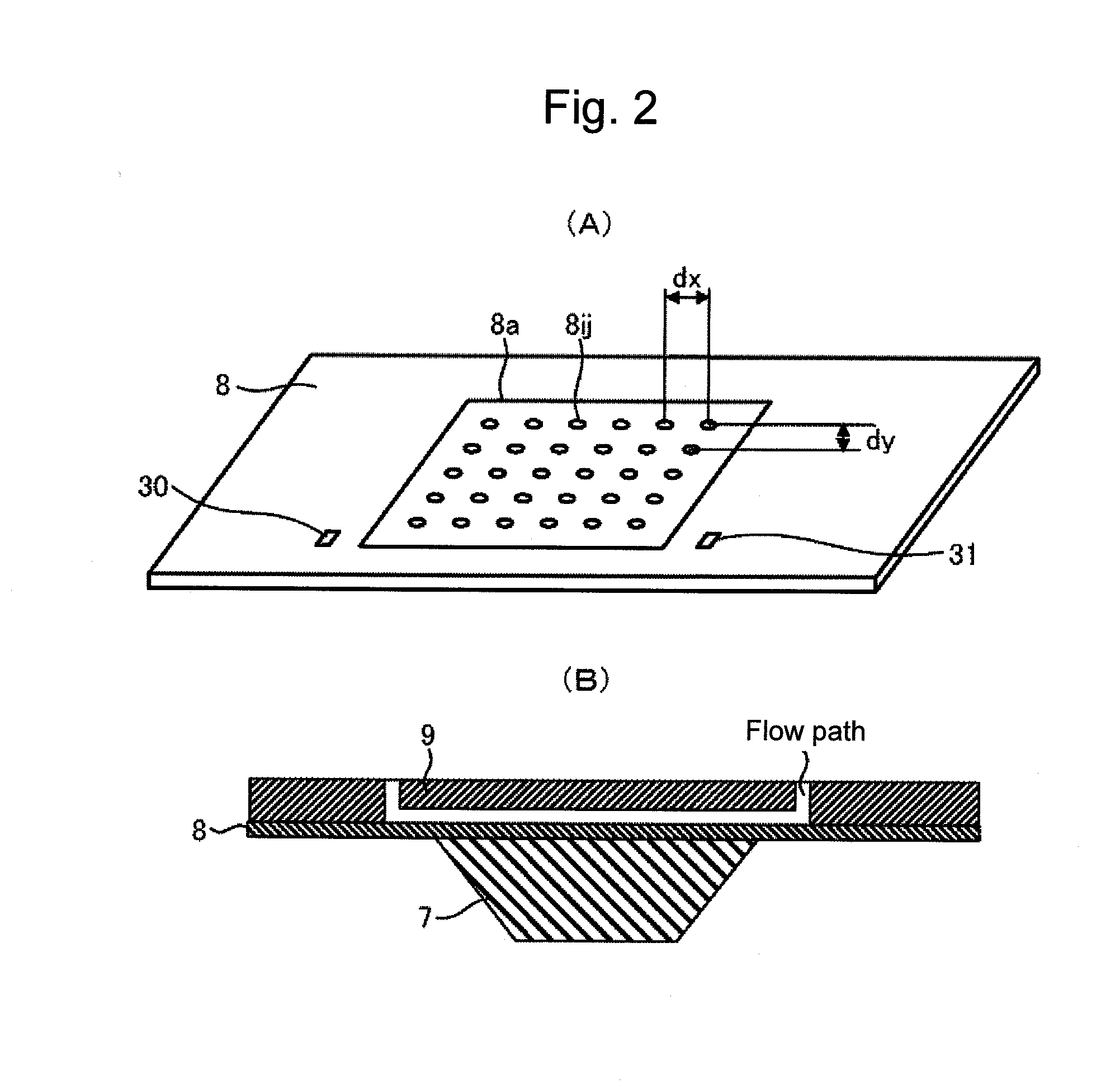
[0054]Description is given of an apparatus and a method for capturing sample DNA fragments to be analyzed molecule by molecule at equal intervals on a substrate surface, elongating the captured fragments substantially for each base, detecting taken-in fluorescent labels molecule by molecule, and thus determining a nucleotide sequence thereof. Specifically, in one cycle, performed are: a step of causing a DNA polymerase reaction using four types of dNTP derivatives which can be each taken into a template DNA as a substrate of a DNA polymerase to stop a DNA chain elongation reaction by the presence of a protecting group, the dNTP derivatives each having a detectable label; then, a step of detecting the taken-in dNTP derivatives by fluorescence detection or the like; and a step of bringing the dNTP derivatives back into an elongatable state. Such a cycle of the steps is repeated to determine the nucleotide sequence of the sample DNA. Note that single-molecule fluorescence detection is ...

embodiment 2

[0092]FIG. 7 shows a configuration according to Embodiment 2 of the present invention. In the present embodiment, DNA sequencing is performed through a gradual elongation reaction using four types of fluorescent materials. An overall configuration and the like are the same as those of FIG. 1.

[0093]Alexa Fluor 488, Cy3, Cy5, and Cy5.5 are used for the fluorescent labels of dNTPs. Various fluorescent materials other than these can also be used therefor. In addition, four types of dNTPs labeled with one fluorescent material can also be used therefor. A laser beam from a laser apparatus 101c for fluorescence excitation (solid-state laser, 505 nm: for excitation of Alexa Fluor 488 and Cy3) is circularly polarized through a λ / 4 wave plate 102c. A laser beam from a laser apparatus 101d for fluorescence excitation (semiconductor laser, 635 nm: for excitation of Cy5 and Cy5.5) is circularly polarized through a λ / 4 wave plate 102d. The two laser beams are superimposed on each other by a mirro...

embodiment 3

[0099]Another example combination of fluorescent materials is described.

[0100]A similar operation to that of Embodiment 1 can be easily performed using, as the fluorescent materials, five types of Alexa Fluor 488, Alexa Fluor 532, Alexa Fluor 568, Alexa Fluor 594, and Alexa Fluor 647, and these five types of fluorescent materials can be easily identified on the basis of the fluorescence intensity ratios, using the same dichroic mirror as that of FIG. 3(C).


PUM

PropertyMeasurementUnit
transmittanceaaaaaaaaaa
thicknessaaaaaaaaaa

Abstract

Provided are a method and an apparatus for easily identifying and detecting fluorescent material types captured in respective reaction regions of a substrate, particularly, a method and an apparatus for identifying and measuring the fluorescence intensities of a plurality of fluorescent materials using a small pixel count. The fluorescence intensities of four or more types of fluorescent materials are divided by a dividing section at ratios different at least for each fluorescence maximum wavelength range, and are detected by at least one detector including pixels for detecting the light fluxes divided at the different ratios. The type of the fluorescent material is determined on the basis of the ratio of the detected fluorescence intensity of the same detection portion, and the fluorescence intensity is measured.

Description

TECHNICAL FIELD[0001]The present invention relates to a light analyzing apparatus, for example, a light measuring / analyzing apparatus which irradiates light to DNA, RNA, or biologically relevant substances such as proteins and cells to perform light analysis.BACKGROUND ART[0002]Up to now, there has been proposed a method of radiating excitation light to an object disposed on a surface of a substrate to observe the shape of the object. For example, Patent Literature 1 describes an apparatus which radiates excitation light outputted from an excitation light source to a transparent substrate, causes total reflection of the excitation light inside of the transparent substrate to thereby generate an evanescent wave on a substrate surface, and detects scattered light of the evanescent wave due to a sample on the substrate. Note that the apparatus described in Patent Literature 1 does not disperse the scattered light.[0003]In addition, for example, Patent Literature 2 describes an apparatu...

Claims


Application Information

Patent Timeline
Patent Type & Authority Applications(United States)
IPC IPC(8): G01N21/64
CPCG01N21/6428G01N21/6452G01N2021/6441G01N2021/6419G01N2021/6421G01N2021/6417
Inventor TAKAHASHI, SATOSHISONEHARA, TSUYOSHIHAGA, TAKANOBU
Owner HITACHI HIGH-TECH CORP
Why Eureka
Try Eureka