

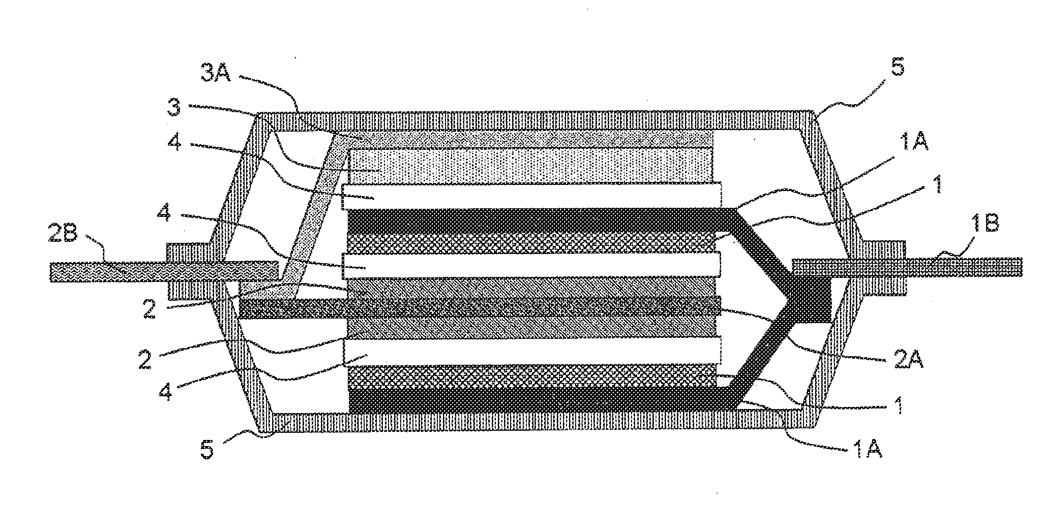
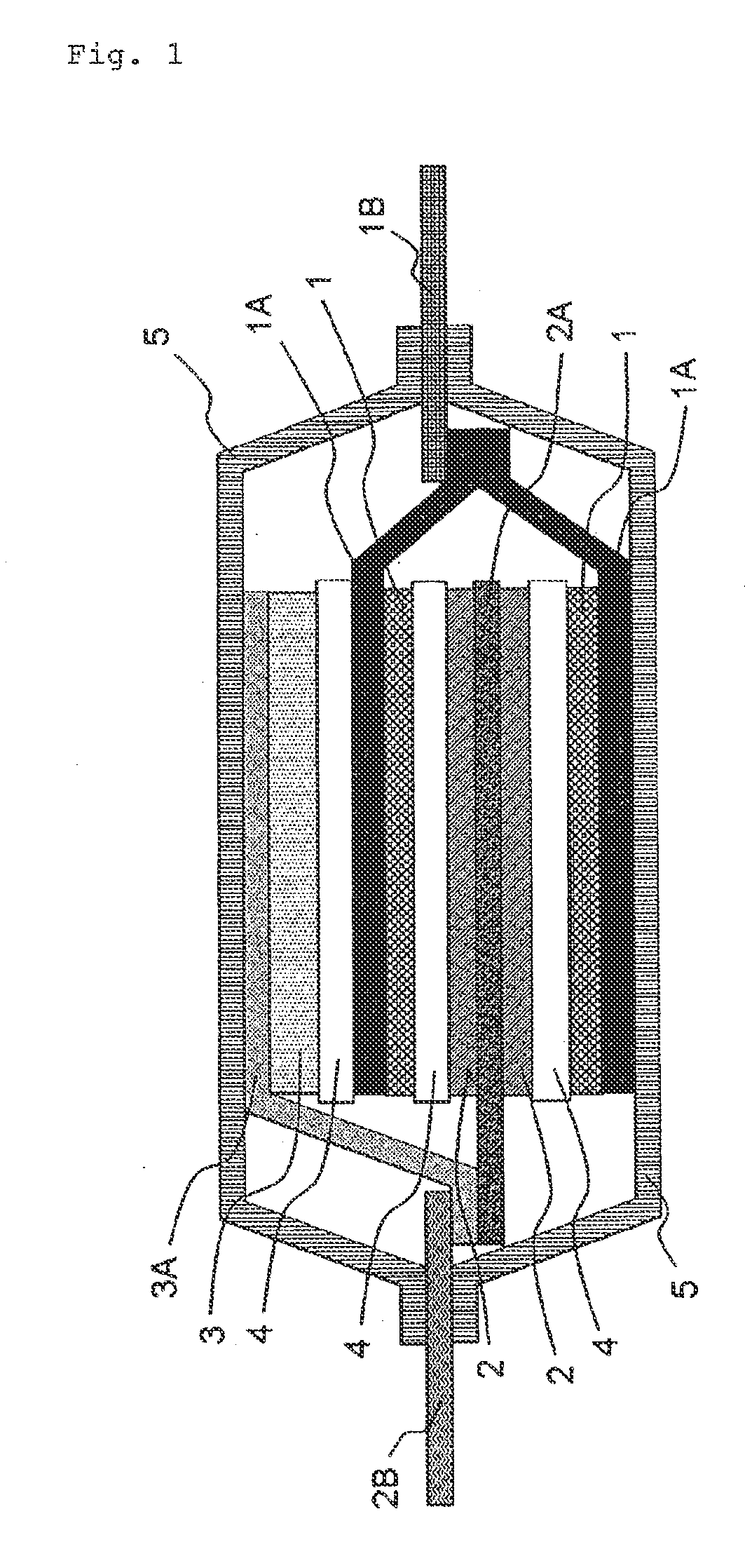
Electricity storage device
a technology of energy storage and energy density, which is applied in the direction of non-aqueous electrolyte cells, cell components, sustainable manufacturing/processing, etc., can solve the problems of increasing the cost of energy storage devices, the safety of automobiles is not widely used, and the safety of energy storage devices is not widely used. , to achieve the effect of low environmental load, high energy density and high output characteristics
- Summary
- Abstract
- Description
- Claims
- Application Information
AI Technical Summary
Benefits of technology
Problems solved by technology
Method used
Image

Examples
synthesis example 1
Synthesis of Nitroxyl Compound (PTMA)
[0047]20 g (0.089 mol) of a 2,2,6,6-tetramethylpiperidine methacrylate monomer was placed in a 100 ml eggplant flask equipped with a reflux tube, and dissolved in 80 ml of dry tetrahydrofuran. 0.29 g (0.00187 mol) of azobisisobutyronitrile (AIBN) (monomer / AIBN mass ratio=50 / 1) was added thereto, and the mixture was stirred under an argon atmosphere at 75 to 80° C. After 6 hours of reaction, the material was allowed to cool to room temperature. The polymer was precipitated in hexane, filtered off, and dried under reduced pressure to obtain 18 g of poly(2,2,6,6-tetramethylpiperidine methacrylate) (yield: 90%). Next, 10 g of the obtained poly(2,2,6,6-tetramethylpiperidine methacrylate) was dissolved in 100 ml of dry dichloromethane. 100 ml of a solution of 15.2 g (0.088 mol) of m-chloroperbenzoic acid in dichloromethane was dropped therein with stirring at room temperature over 1 hour. The mixture was further stirred for 6 hours, and then, the prec...
synthesis example 2
Synthesis of Nitroxyl Compound Having Crosslinked Structure (Crosslinked PTMA-1)
Crosslinking Agent: Ethylene Glycol Dimethacrylate
Degree of Crosslinking: 0.5 mol %
[0048]20 g (0.089 mol) of a 2,2,6,6-tetramethylpiperidine methacrylate monomer was placed in a 100 ml eggplant flask equipped with a reflux tube, and dissolved in 80 ml of dry tetrahydrofuran. 0.29 g (0.00187 mol) of azobisisobutyronitrile (AIBN) (monomer / AIBN mass ratio=50 / 1), and ethylene glycol dimethacrylate as the crosslinking agent were added thereto, and the mixture was stirred under an argon atmosphere at 75 to 80° C. After 6 hours of reaction, the material was allowed to cool to room temperature. The polymer was precipitated in hexane, filtered off, and dried under reduced pressure to obtain 18 g of poly(2,2,6,6-tetramethylpiperidine methacrylate) (yield: 90%). Next, 10 g of the obtained poly(2,2,6,6-tetramethylpiperidine methacrylate) was dissolved in 100 ml of dry dichloromethane. 100 ml of a solution of 15.2 g ...
synthesis examples 3 to 41
Synthesis of Nitroxyl Compounds Having Crosslinked Structure (Crosslinked PTMAs-2 to 40)
[0049]Crosslinked PTMAs were synthesized by an operation similar to that of the method for synthesizing crosslinked PTMA-1, using any of eight types, ethylene glycol dimethacrylate, butanediol dimethacrylate, hexanediol dimethacrylate, nonanediol dimethacrylate, decanediol dimethacrylate, dodecanediol dimethacrylate, diethylene glycol dimethacrylate, and triethylene glycol dimethacrylate, as the crosslinking agent, with a degree of crosslinking in the range of 0.5 to 6 mol %. The structure of the obtained polymers was confirmed by IR. The obtained crosslinked products were insoluble in methanol, ethanol, acetone, ethyl acetate, tetrahydrofuran, dimethylformamide, and dimethyl sulfoxide. PTMA and crosslinked PTMAs synthesized in Synthesis Examples 1 to 41 are shown in the following Table 1. The solubility in organic solvents indicates solubility in methanol, ethanol, acetone, ethyl acetate, tetrah...
PUM
| Property | Measurement | Unit |
|---|---|---|
| ion conductivity | aaaaa | aaaaa |
| temperature | aaaaa | aaaaa |
| glass transition temperature | aaaaa | aaaaa |
Abstract
Description
Claims
Application Information