Electromagnetic shielding sheet technical field

a technology of electromagnetic shielding and shielding sheets, applied in the field of electromagnetic shielding sheets, can solve the problems of electromagnetic wave leakage from electronic devices on digital devices, decrease in electromagnetic wave shielding properties, and increase in metal coatings, so as to reduce the amount of metal coating, improve the adhesion of metal coatings, and reduce the thickness of bases

Active Publication Date: 2012-05-10
ASAHI KASEI FIBERS CORPORATION
View PDF5 Cites 19 Cited by
  • Summary
  • Abstract
  • Description
  • Claims
  • Application Information

AI Technical Summary

Benefits of technology

[0026]The electromagnetic shielding sheet of the present invention improves adhesion of a metal coating by arranging ultrafine fibers in a middle layer while reducing an increase in thickness of a base after forming the metal coating, reduces the amount of metal coated, and demonstrates superior shielding properties consisting of electromagnetic wave shielding properties of 60 dB or more despite having a small amount of adhered metal. In addition, the electromagnetic shielding sheet of the present invention can be incorporated with a high degree of freedom in a highly integrated electronic device as a high-performance electromagnetic shielding sheet having reduced thickness and lighter weight due to the strength of the sheet.

Problems solved by technology

The effects of electromagnetic waves leaking from electronic devices on digital devices has come to be a problem in recent years with the rapid advance of the use of digital technology in such electronic devices.
In addition, not only have electromagnetic waves conventionally been known to cause erroneous operation by having an effect on electric signals flowing through electronic circuits, but there are also concerns regarding their effect on the body, and electromagnetic shielding materials have been developed as a countermeasure against this.
Although electromagnetic shielding materials that use woven fabrics or non-woven fabrics are used as materials that satisfy these requirements, these fabrics have the problem of causing a decrease in electromagnetic wave shielding properties unless the weight per unit area and thickness of the woven fabric or non-woven fabric per se are increased and the amount of metal coating is also increased.
In this case, however, in order to obtain desired electromagnetic wave shielding properties, there are the problems of an increase in the base thickness after forming the metal coating and an increase in thickness of the metal coating per se.
However, the high level of electrical conductivity of the metal is conversely impaired by resin coating, ultimately resulting in a thick sheet that does not have high electromagnetic wave shielding properties.
However, in the fiber sheets disclosed in these documents, although a high-performance sheet is obtained by using ultrafine fibers, due to the weak strength of the ultrafine fiber sheet, it was unable to be used practically.
Namely, although it is necessary to attach highly electrically conductive metal to polymer fibers in order to enhance electromagnetic wave shielding performance, and electroless plating by a wet method is typically used to obtain high levels of electrical conductivity and adhesiveness, in this process, the electrochemical reaction in the form of plating is repeated for multiple layers, while drying and exposure to a plating bath are also repeated many times. Consequently, the fabric itself ends up tearing or defects end up forming in the fabric during these processes, thereby preventing the obtaining of uniform processing.
In addition, although it is necessary to deposit metal by placing in a vacuum chamber in the case of methods involving metal deposition, strength is unable to be imparted to the fabric at this time causing it to tear or causing defects to form in the fabric.
In addition, in order to ensure reliable adhesion to the fiber surface, it is necessary to use a high vacuum and activate the surface of the fibers, and the fiber fabric was unable to withstand these processes.

Method used

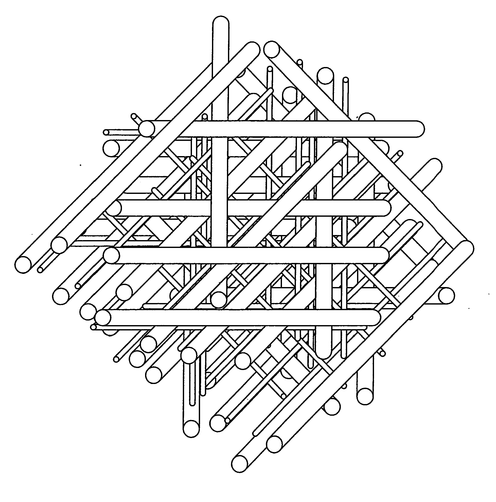
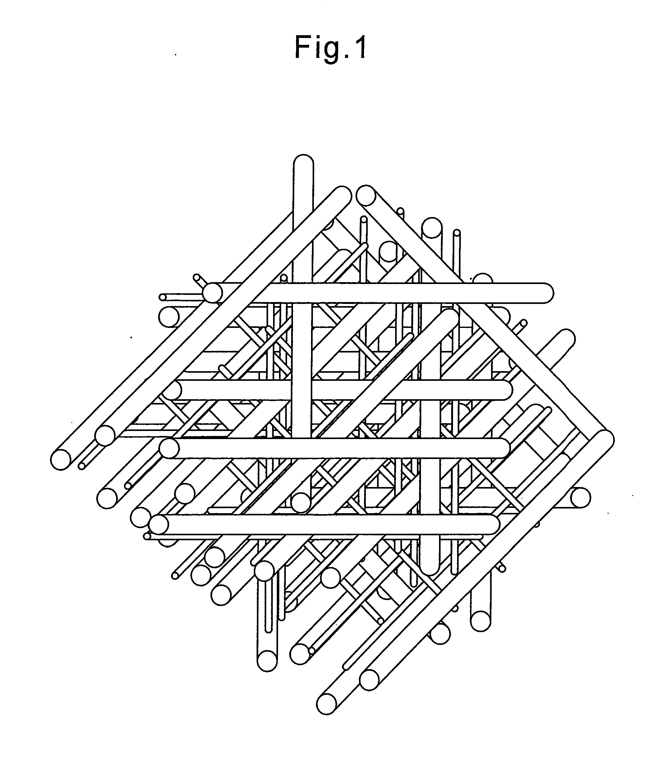
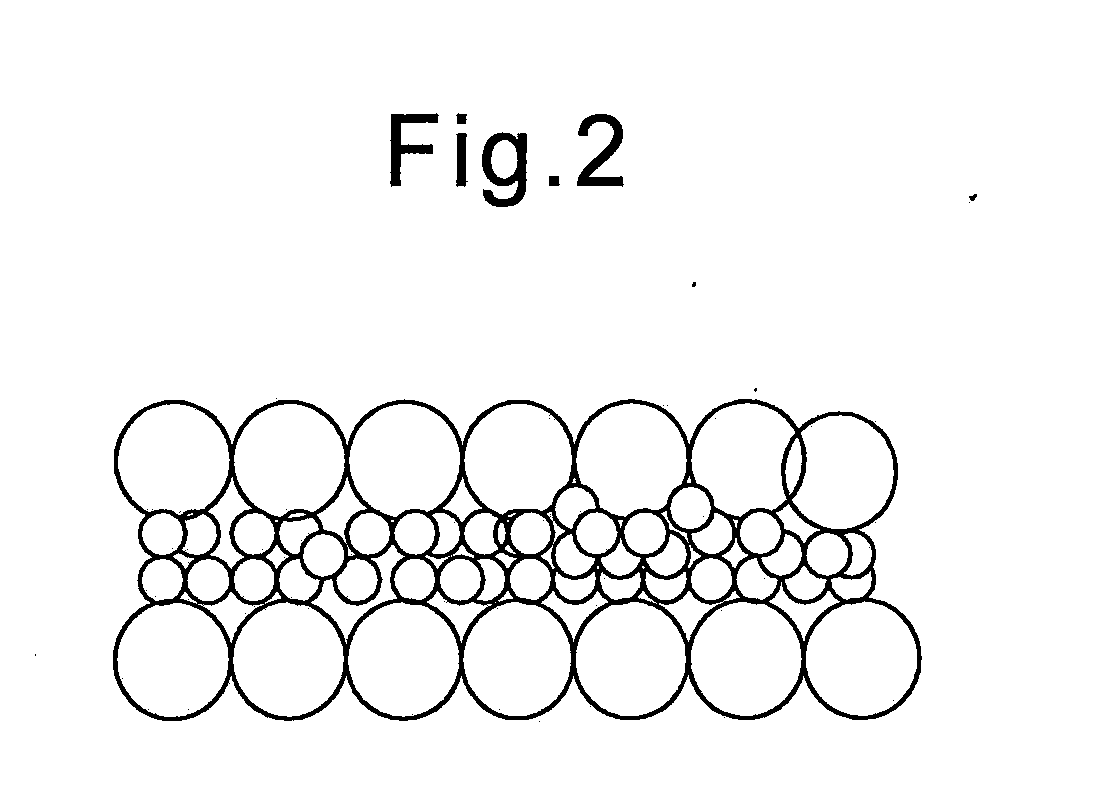

Image

  • Electromagnetic shielding sheet technical field
  • Electromagnetic shielding sheet technical field
  • Electromagnetic shielding sheet technical field

Examples


examples

[0061]Although the following provides a more detailed explanation of the present invention through examples thereof, the present invention is not limited to these examples. In addition, the various physical properties and characteristics of the electromagnetic shielding sheet of the present invention were measured in accordance with the methods indicated below.

[0062](1) Weight per unit area (g / m2): The weight of a sample measuring 24 cm×33 cm was converted to weight per square meter (m2).

[0063](2) Thickness (μm): Thicknesses at 10 locations per 1 m of width were measured in accordance with the method defined in JIS L-1906 followed by determination of the average value thereof. The load was 9.8 kPa.

[0064](3) Average fiber diameter (μm): Enlarged micrographs were taken at a magnification of 500× with an electron microscope, followed by determining the average value for 10 fibers.

[0065](4) Non-woven fabric tensile strength (N / 3 cm): Test pieces having a width of 30 mm and a length of a...

example of

Production of Non-Woven Fabric and Metal Plating

[0090]General-purpose polyethylene terephthalate was extruded with a group of long filaments facing towards the movement capturing surface at a spinning temperature of 300° C. by spun bonding, the fibers were spun at a spinning speed of 3500 m / min and then charged to about 3 μC / g by coronal discharge to adequately open the fibers, and an unbound long filament web composed of filaments having an average fiber diameter of 16 μm and having uniformity on the order of a 5 cm fluctuation rate of 15% or less was prepared on the surface of a capturing net at a weight per unit area of 12.5 g / m2 (Non-Woven Fabric Layer A).

[0091]On the other hand, polyethylene terephthalate (melt viscosity ηsp / c: 0.50) was spun by melt blowing under conditions of a spinning temperature of 300° C., hot air temperature of 320° C. and air discharge rate of 1000 Nm3 / hr / m, followed by blowing ultrafine fibers having an average fiber diameter of 1.6 μm directly towards...

example 1

[0095]The composition of base materials having the fiber diameters and weight per unit areas of the first layer, second layer and third layer of a laminated non-woven fabric composed of polyester fibers obtained according to the aforementioned method is shown in the following Table 1. The electromagnetic shielding sheet obtained in the aforementioned production example demonstrated favorable metal adhesion, a small increase in thickness after metal working of 3 μm, and high shielding properties. The evaluation results are similarly shown in the following Table 1. The resulting electromagnetic shielding sheet had an extremely thin thickness after metal forming of 30 μm and demonstrated high shielding properties (65 dB).


PUM

PropertyMeasurementUnit
diameteraaaaaaaaaa
diameteraaaaaaaaaa
thicknessaaaaaaaaaa

Abstract

Disclosed is an electromagnetic shielding sheet that has a smaller increase in the thickness of a base after the formation of a metal coating film when compared with conventional electromagnetic shielding sheets, and which has excellent electromagnetic wave shielding properties despite a small amount of adhered metal. According to the present invention, the electromagnetic shielding sheet can endure metal working processes and has high electromagnetic wave shielding properties, resulting in a thin, very flexible fabric sheet. Specifically disclosed is an electromagnetic shielding sheet which is composed of a laminated non-woven fabric that has at least a first layer and a second layer, and which is characterized in that the first layer is a layer of thermoplastic synthetic fibers having a fiber diameter of 6 μm to 50 μm, the second layer is a layer of ultrafine fibers having a fiber diameter of 0.1 μm to 5.0 μm, and a metal is adhered to at least one surface of the sheet.

Description

TECHNICAL FIELD[0001]The present invention relates to an electromagnetic shielding sheet that has favorable electromagnetic wave shielding properties and enables the thickness of a base to be reduced.BACKGROUND ART[0002]The effects of electromagnetic waves leaking from electronic devices on digital devices has come to be a problem in recent years with the rapid advance of the use of digital technology in such electronic devices. In addition, not only have electromagnetic waves conventionally been known to cause erroneous operation by having an effect on electric signals flowing through electronic circuits, but there are also concerns regarding their effect on the body, and electromagnetic shielding materials have been developed as a countermeasure against this.[0003]In addition, simultaneous to being required to demonstrate a high level of electromagnetic wave shielding (electromagnetic wave shielding properties), materials that have flexibility and bending resistance, are thin and ...

Claims


Application Information

Patent Timeline
Patent Type & Authority Applications(United States)
IPC IPC(8): H05K9/00D04H3/14D04H5/06
CPCB32B5/022D04H5/06B32B2250/02B32B2250/03B32B2250/20B32B2250/40B32B2255/02B32B2255/205B32B2262/0284B32B2305/20B32B2305/28B32B2307/202B32B2307/718B32B2457/00D06M11/83D06M17/00D06M2101/32H05K9/0084D04H3/14B32B5/26Y10T442/657Y10T442/659B32B15/14D04H1/54H05K9/00
Inventor KATO, KAZUFUMISHIKATA, KAZUAKIOBI, RUMINAUENO, IKUO
Owner ASAHI KASEI FIBERS CORPORATION
Why Eureka
Try Eureka