Environmental Cell for Charged Particle Beam System

a charge-beam system and charge-beam technology, applied in the field of charge-beam systems, can solve the problems of interference with the operation of hpsem, problems such as problems such as biological samples that are not suitable for observation in high vacuum, and can not be used in high vacuum. , to achieve the effect of rapid cell environment switching, flexible, and rapid pumping of the cell interior

Active Publication Date: 2012-05-10
FEI CO
View PDF19 Cites 44 Cited by
  • Summary
  • Abstract
  • Description
  • Claims
  • Application Information

AI Technical Summary

Benefits of technology

[0020]In one embodiment, a cell is comprised of two parts, and upper part that is fixed relative to the electron beam column and contains a pressure limiting aperture that restricts gas flow into the column, and a lower part which is mounted on a moveable stage of a conventional high vacuum charged particle beam system. A sliding contact seal between the upper and lower parts of the cell allows relative movement between the lower and upper parts. Stage translation in the plane normal to the electron beam axis enables sample navigation without the need for a sub-stage inside the cell, and translation along the beam axis enables rapid switching of the cell environment to that of the surrounding vacuum chamber by opening the sliding contact seal to enable more rapid pumping of the cell interior. The axial motion of the lower part of the cell away from the upper part and the column also frees up space between the sample and the column, enabling the insertion of a device such as a parabolic mirror between the sample and the column, thereby enabling analysis of a sample by techniques such as cathodoluminescence and photoluminescence spectroscopy before and after processing in the gaseous environment of the cell. In some embodiments, the upper part of the cell is mounted on a retraction mechanism which can retract the upper part thereby freeing up further space around the sample, enabling the insertion of devices such as a gas injection capillary to deliver a process gas to a small region of a sample in a high vacuum process chamber, or an x-ray collector used for x-ray analysis of the sample. Embodiments of the invention enable flexible, rapid processing and analysis without exposing the sample to the laboratory atmosphere, without vacuum transfer devices that slow down process workflow and increase cost and complexity, and without the need to make high vacuum process and analysis devices compatible with the chemically aggressive environments encountered in the cell.

Problems solved by technology

However, wet samples such as biological samples are not suitable for observation in a high vacuum.
Such samples experience evaporation of their fluid content in the vacuum before an accurate image can be obtained, and the evaporated gas interferes with the primary electron beam.
While an HPSEM can observe moist biological samples, problems still exist with such observations.
Such condensation can interfere with the operation of HPSEM, as well as cause corrosion and contamination.
Conventional HPSEMs are not well adapted for efficient beam chemistry.
One problem with using a HPSEM system for beam chemistry is the presence of impurities such as H2O inside the sample chamber.
A problem with this approach is that the second and third steps and subsequent beam chemistry process steps cause an increase in the concentration of gaseous impurities such as H2O inside the sample chamber up to a pressure well above the initial base pressure of 10−5 mbar.
The impurities do, however, interfere with beam chemistry because molecules such as H2O and O2 react with and cause the decomposition of deposition and etch precursors such as most organometallics, WF6, MoF6, Pt(PF3)4, XeF2, F2 and Cl2.
This is, however, undesirable as it increases the gas flow rate into the column and decreases the maximum usable sample chamber pressure.
This, however, is also undesirable as it increases the consumption and exhaust rates of precursor gases, which are often expensive and toxic, and reduces the lifetime of the roughing pump.
These approaches are, however, incompatible with the cost and flexibility expected of commercial variable pressure SEM (VPSEM) systems.
Another problem with using a HPSEM system for beam chemistry is the considerable time required to introduce and evacuate gases from the sample chamber.
It takes a considerable amount of time for the gas to reach an equilibrium pressure, particularly if the vapor pressure of the beam chemistry precursor is similar to the desired operating pressure of the sample chamber.
The above problem is compounded when a process entails injecting multiple process gases into the sample chamber.
The pressure gauge typically measures the total pressure in the sample chamber and is incapable of separately measuring the partial pressures of multiple process gases in a mixture.
Thus, it is difficult to know when the desired partial pressure of each of the gases has been achieved.
If some process gas remains in the chamber during imaging, the sample may be unintentionally modified by the beam during the imaging operation.
Because of the considerable time required to fully evacuate one gas and then to reach equilibrium pressure with another gas, such multiple step operations are not practical in an HPSEM.
The processing time is further increased in some cases because the molecules of some gases used in beam chemistry tend to have very long residence times on the chamber walls, and take longer to fully evaporate and to be removed from the sample chamber.
Another reason why HPSEMs are not generally used for beam chemistry is that corrosive process gases can degrade the HPSEM components.
For example, certain process gases associated with beam chemistry can react spontaneously with components such as plastic tubing and are very dangerous to human health.
Gases like XeF2 and MoF6 can make plastic gas tubing brittle and eventually cause leaks of dangerous gases into the surrounding environment.
However, the range of studies that can be performed in a HPSEM is limited by the abovementioned impurities, such as H2O and O2, which are responsible for the VPSEM base pressure.

Method used


Image

  • Environmental Cell for Charged Particle Beam System
  • Environmental Cell for Charged Particle Beam System
  • Environmental Cell for Charged Particle Beam System

Examples


Embodiment Construction

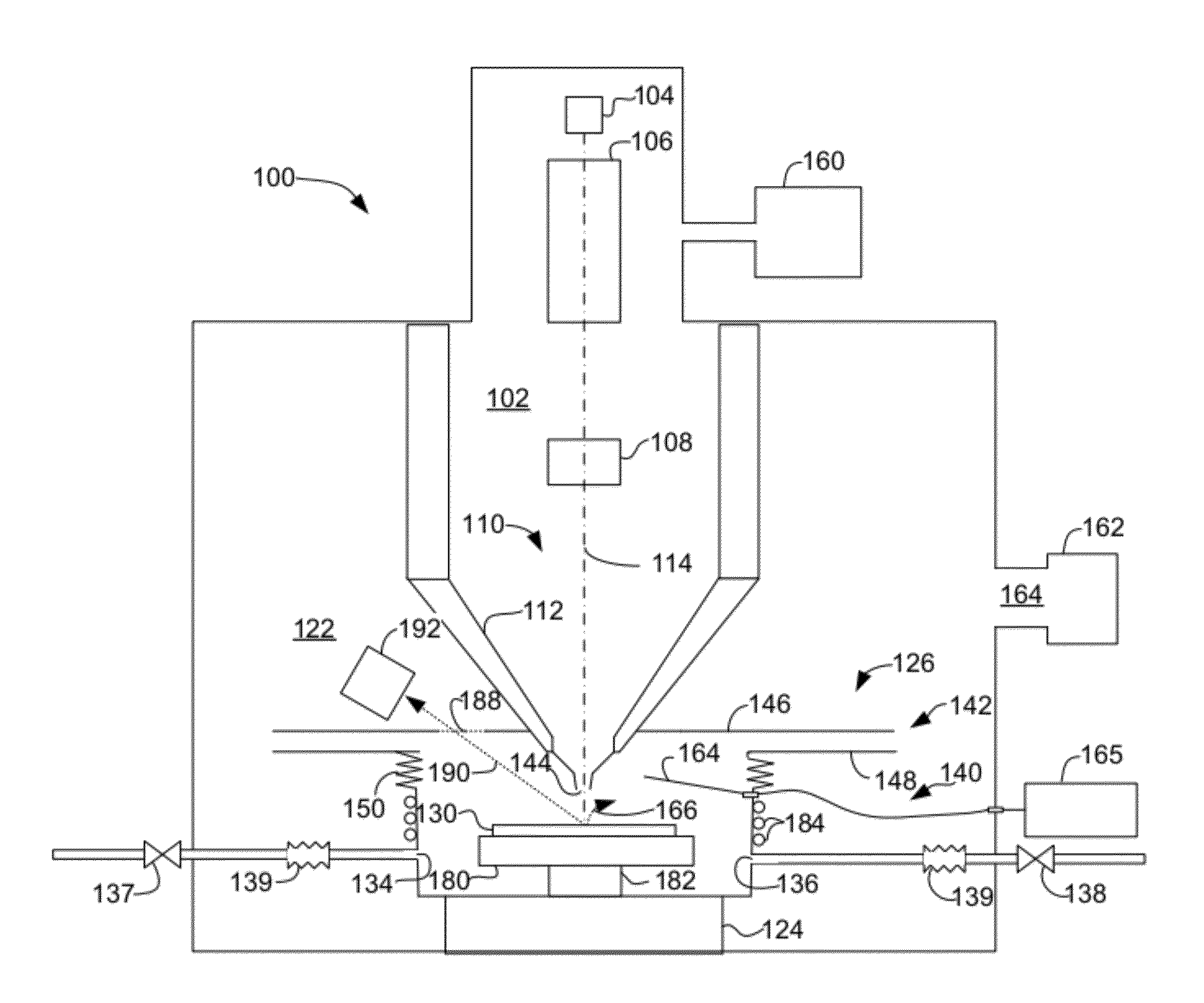
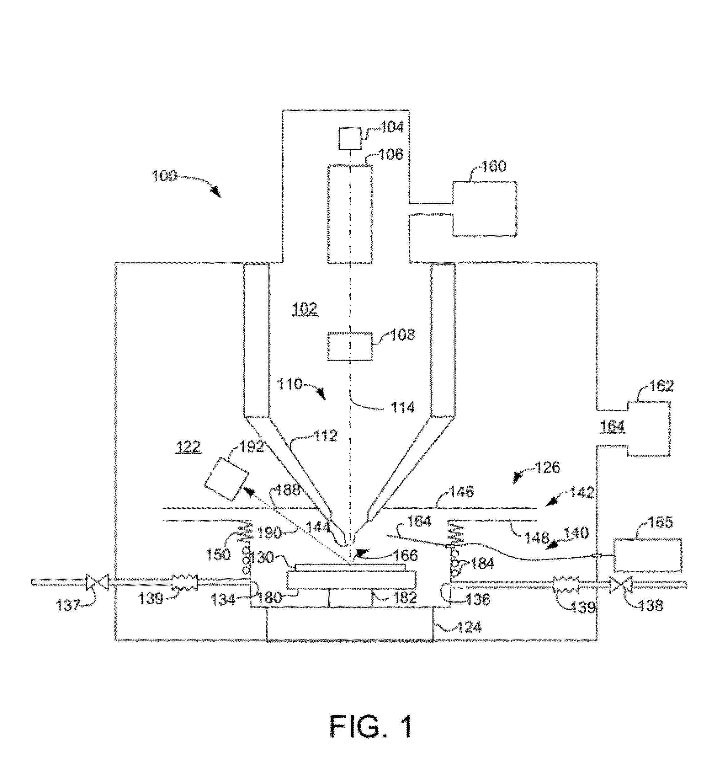
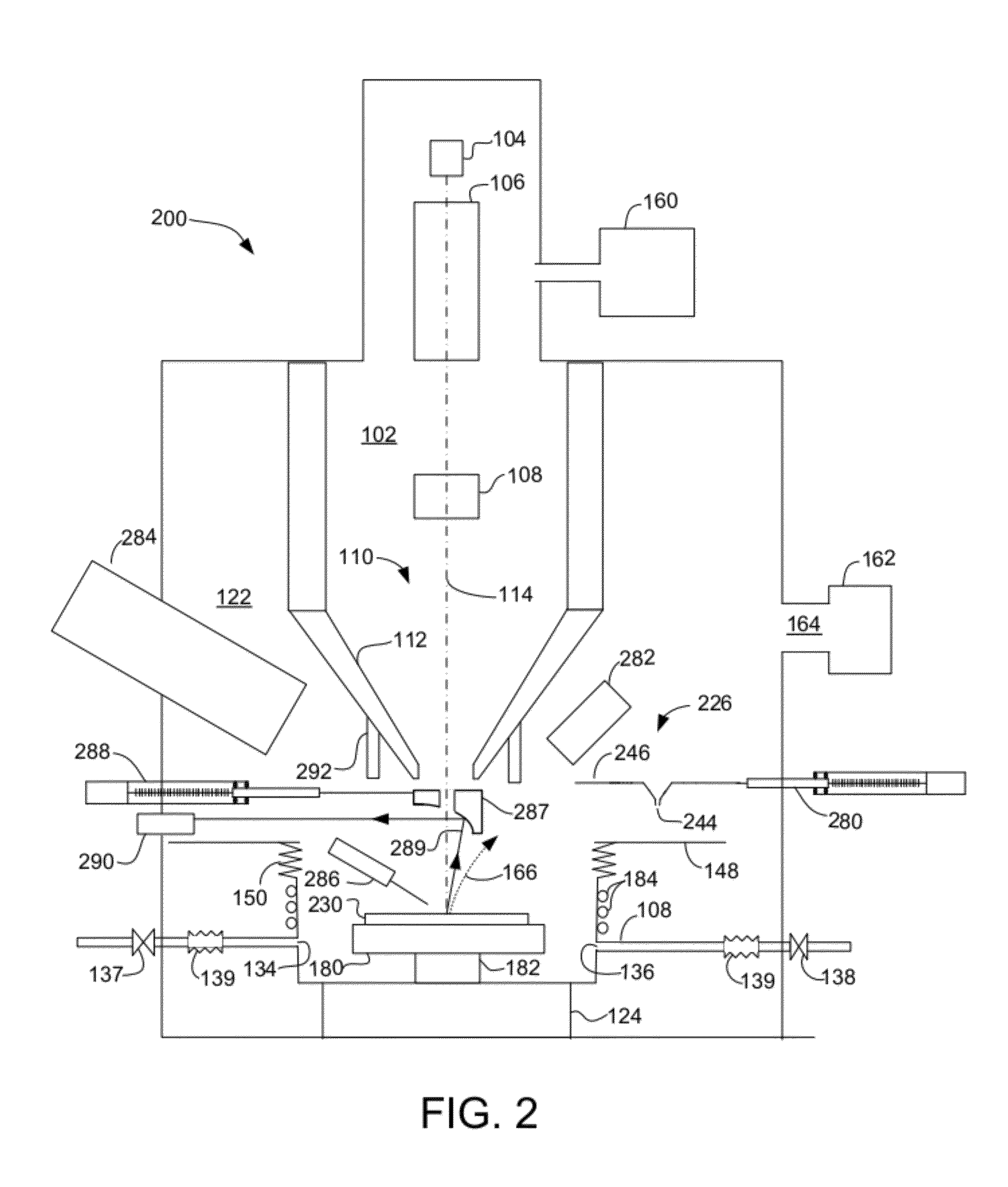
[0034]One aspect of embodiments of the present invention is a charged particle beam system that provides for processing a sample in a gaseous environment. Various embodiments of the invention may provide additional capabilities. In one embodiment, the invention provides an environmental cell for processing a work piece in a relatively high pressure in a charged particle beam system. The cell environment may include one or more gas inlets and outlets and a secondary electron detector that uses gas ionization cascade amplification. In some embodiments, the cell is configurable to remove cell portions, such as a cell lid or one or more cell walls, to facilitate various types of processing or analysis and flexible process workflows in addition to high pressure scanning electron microscopy.

[0035]One preferred embodiment includes a gas seal that allows an environmental cell mounted on a sample stage to be moved independently of the pressure limiting aperture that maintains a higher pressu...


PUM

PropertyMeasurementUnit
pressureaaaaaaaaaa
pressureaaaaaaaaaa
pressureaaaaaaaaaa

Abstract

An environmental cell for a charged particle beam system allows relative motion between the cell mounted on an X-Y stage and the optical axis of the focusing column, thereby eliminating the need for a sub-stage within the cell. A flexible cell configuration, such as a retractable lid, permits a variety of processes, including beam-induced and thermally-induced processes. Photon yield spectroscopy performed in a charged particle beam system and using gas cascade amplification of the photoelectrons allows analysis of material in the cell and monitoring of processing in the cell. Luminescence analysis can be also performed using a retractable minor.

Description

TECHNICAL FIELD OF THE INVENTION [0001]The present invention relates to charged particle beam systems, and in particular, to charged particle beam systems that allow a work piece to be processed in a reactive gaseous environment.BACKGROUND OF THE INVENTION[0002]In a scanning electron microscope (“SEM”), a primary beam of electrons is scanned upon a region of a sample that is to be investigated. The energy released in the impact of the electrons with the sample causes the liberation of other charged particles in the sample. The quantity and energy of these secondary particles provide information on the nature, structure and composition of the sample. The term “sample” is traditionally used to indicate any work piece being processed or observed in a charged particle beam system and the term as used herein includes any work piece and is not limited to a sample that is being used as a representative of a larger population. The term “secondary electrons” as used herein includes backscatt...

Claims


Application Information

Patent Timeline
Patent Type & Authority Applications(United States)
IPC IPC(8): G01N23/22G21K5/04
CPCH01J37/18H01J37/20H01J37/244H01J2237/2445H01J2237/2001H01J2237/2003H01J2237/024
Inventor NOVAK, LIBORUNCOVSKY, MAREKTOTH, MILOSCAFOUREK, MARTINPARKER, WILLIAMSTRAW, MARCUSEMERSON, MARK
Owner FEI CO
Why Eureka
Try Eureka