Mems-based optical image scanning apparatus, methods, and systems

a scanning apparatus and optical image technology, applied in the field of mems-based optical image scanning apparatus, methods, and systems, can solve the problems of large optical system, specimens cannot be observed in vivo by the standard bulky confocal or nlo microscope, optical confocal scanning microscope is smaller than the standard confocal microscope, and remains too large for in vivo imaging, etc., to achieve minimal lateral shift, large scanning angle, and large vertical displacement

Inactive Publication Date: 2012-06-07
UNIV OF FLORIDA RES FOUNDATION INC
View PDF19 Cites 49 Cited by
  • Summary
  • Abstract
  • Description
  • Claims
  • Application Information

AI Technical Summary

Benefits of technology

[0016]The MEMS mirror and MEMS lens can have similar structures (differing in the mirror plate and lens portions) and can be actuated by electrothermal act

Problems solved by technology

However, standard confocal and NLO microscopes have large-sized optical systems.
Therefore, specimens cannot be observed in vivo by the standard bulky confocal or NLO microscopes.
The fiber optical confocal scanning microscope is smaller than standard confocal microscopes, but remains too large for in vivo imaging.
Though this method provides a fiber optic approach to imaging, the microscope objectives limit the miniaturization capabilities of this design, making it difficult to meet the desired dimension for endoscopic imaging.
In addition, the distortion of images may be induced

Method used


Image

  • Mems-based optical image scanning apparatus, methods, and systems
  • Mems-based optical image scanning apparatus, methods, and systems
  • Mems-based optical image scanning apparatus, methods, and systems

Examples


Embodiment Construction

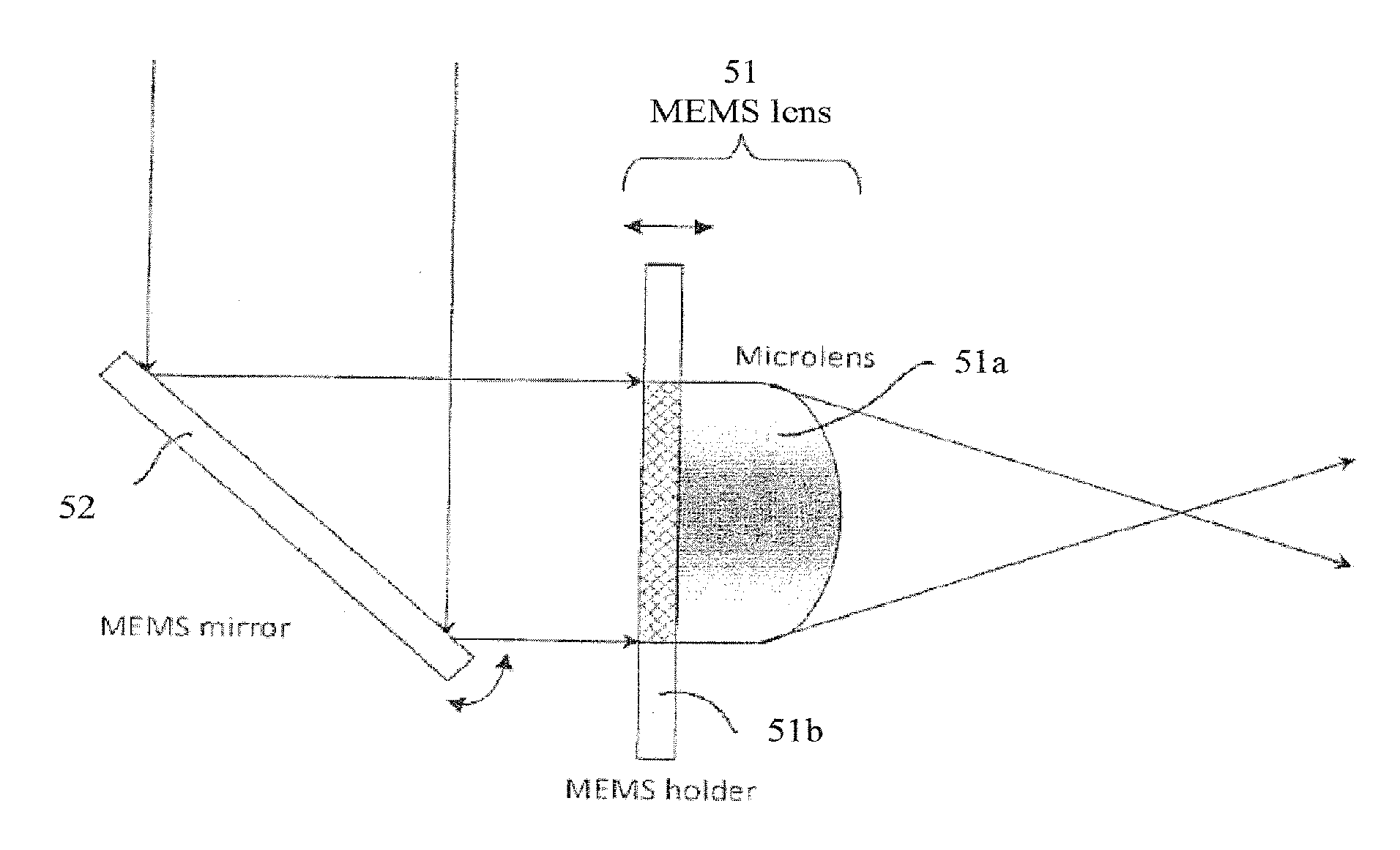
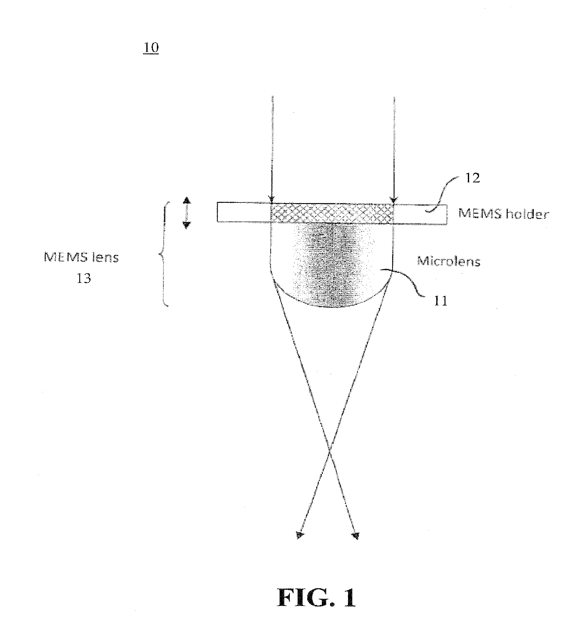
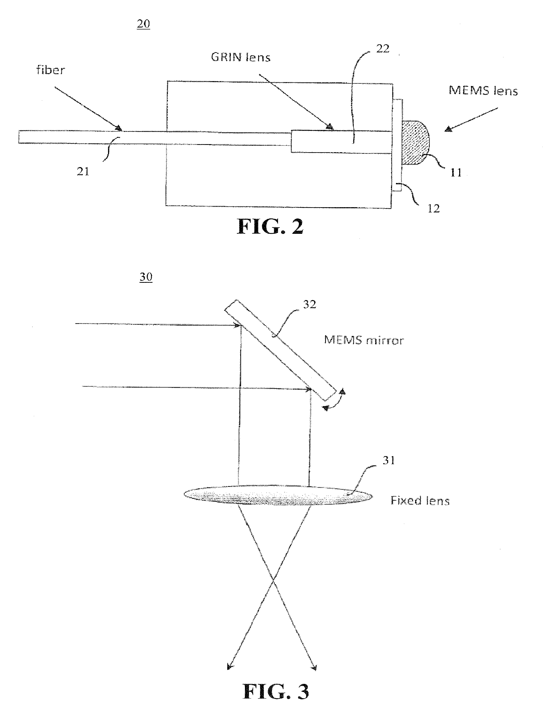
[0035]Embodiments of the present invention provide a MEMS-based scanning apparatus. In accordance with embodiments of the present invention, miniature light scanners for endoscopic confocal or NLO imaging based on MEMS mirrors and a MEMS lens are provided. Confocal microscopy and NLO microscopy are powerful imaging techniques now routinely used in many fields, such as biomedical imaging, chemical analysis and industrial inspection. Their major advantages are high contrast and high resolution capabilities, and the optical sectioning capacity. However, since standard confocal and NLO microscopes have large optical systems, the tissues cannot be observed in vivo by a standard bulky confocal or NLO microscope. Instead, tissues are removed from the living body and mounted onto microscope slides for in vitro observation.

[0036]To realize in vivo real-time confocal or NLO imaging, the optical scanning system is miniaturized. By using optical fibers as a transmission medium, a first step of ...


PUM


Abstract

Disclosed are MEMS-based optical image scanners and methods for imaging using the same. According to one embodiment, a 3-D scanner for endoscopic imaging is provided, which includes a MEMS mirror for 1-D or 2-D lateral scanning and a MEMS lens for scanning along the optical axis to control the focal depth. The MEMS lens can be a microlens bonded to a MEMS holder. Both the MEMS holder and the MEMS mirror can be electrothermally actuated. A single-mode fiber can be used for both delivering the light to and receiving the returning light from an object being examined.

Description

CROSS-REFERENCE TO RELATED APPLICATION[0001]This application claims the benefit of U.S. Provisional Application Ser. No. 61 / 239,619 filed Sep. 3, 2009, which is hereby incorporated by reference in its entirety, including all figures, tables and drawings.[0002]The subject invention was made with government support under Grant Nos. 0423557 and 0818473 awarded by the National Science Foundation. The government has certain rights in the invention.BACKGROUND OF INVENTION[0003]Confocal microscopy and nonlinear optical (NLO) microscopy are powerful imaging techniques that are routinely used in many fields such as biological observation, chemical analysis and industrial inspection.[0004]In confocal microscopy, a light source, such as a laser beam, is focused by an objective lens into a small focal volume within or on the surface of a specimen. Scattered and reflected light from the illuminated spot is then re-collected by the objective lens. A beam splitter is used to direct the light from ...

Claims


Application Information

Patent Timeline
IPC IPC(8): G02B23/26G02B26/10
CPCA61B1/00096A61B1/00172G01B11/24A61B5/0068A61B5/0084A61B5/0066
Inventor XIE, HUIKAILIU, LIN
Owner UNIV OF FLORIDA RES FOUNDATION INC
Why Eureka
Try Eureka