Systems and methods for separating condensable vapors from gases by direct-contact heat exchange

a technology of condensable vapor and heat exchange, which is applied in the direction of separation process, lighting and heating apparatus, heating types, etc., can solve the problems of inability to adopt utility-scale, unacceptable decrease in the total efficiency of the power plant, etc., and achieve the effect of facilitating the separation of solid co2 particles

Active Publication Date: 2012-06-21
U S BANK TRUST CO NAT ASSOC
View PDF1 Cites 26 Cited by
  • Summary
  • Abstract
  • Description
  • Claims
  • Application Information

AI Technical Summary

Benefits of technology

[0010]The use of a DCHE produces a net effect of exchanging heat between the desublimating process stream and the NVHEL. However, it accomplishes this without subjecting any stationary heat transfer surface to frosting, fouling, or any other heat-transfer-inhibiting mass accumulation. The NVHEL is the heat transfer surface on which the solids can accumulate, and their accumulation in the liquid does not impede heat transfer in the DCHE. The heat exchange in the DCHE is by direct contact and is more efficient than through a heat exchange wall. Furthermore, the DCHE is a liquid-fluid system, which is far more efficient than gas-fluid systems in other heat exchangers.
[0017]In one embodiment, the DCHE can be operated at modest or high pressure such that the exiting light-gas stream can be further cooled by expansion downstream. In one embodiment, a separated light-gas stream having a pressure greater than about 5 psi, greater than about 20 psi, or greater than about 50 psi is expanded to cool the separated light-gas stream to a temperature that is below the temperature of the RHE. This additional cooling of the separated light-gas stream can cause desublimation of a residual portion of condensable vapors in the separated light-gas stream. A solids separation apparatus can remove solids that form in the expansion of the separated light-gas stream. The cooled separated light-gas stream can then be transferred to the RHE, thereby drawing heat from the recirculating NVHEL.
[0021]Increasing the contact surface area between the NVHEL and the process stream can facilitate desublimation. To maximize the contact surface area, the system described herein may include a DCHE vessel with a packing material such as screens, discs, or variably shaped three dimensional items.
[0023]One embodiment of the system pressurizes the NVHEL-CO2 slurry prior to complete separation of the NVHEL from the CO2, taking advantage of the ability of the slurry to pass through pumps. The slurry pump both increases the solid pressure to the point it can melt to form a liquid and facilitates separation of the solid CO2 particles from the NVHEL.

Problems solved by technology

However, it has not been adopted in utility-scale power plants, primary because the technology causes an unacceptable decrease in the total efficiency of the power plant.

Method used


Image

  • Systems and methods for separating condensable vapors from gases by direct-contact heat exchange
  • Systems and methods for separating condensable vapors from gases by direct-contact heat exchange
  • Systems and methods for separating condensable vapors from gases by direct-contact heat exchange

Examples


Embodiment Construction

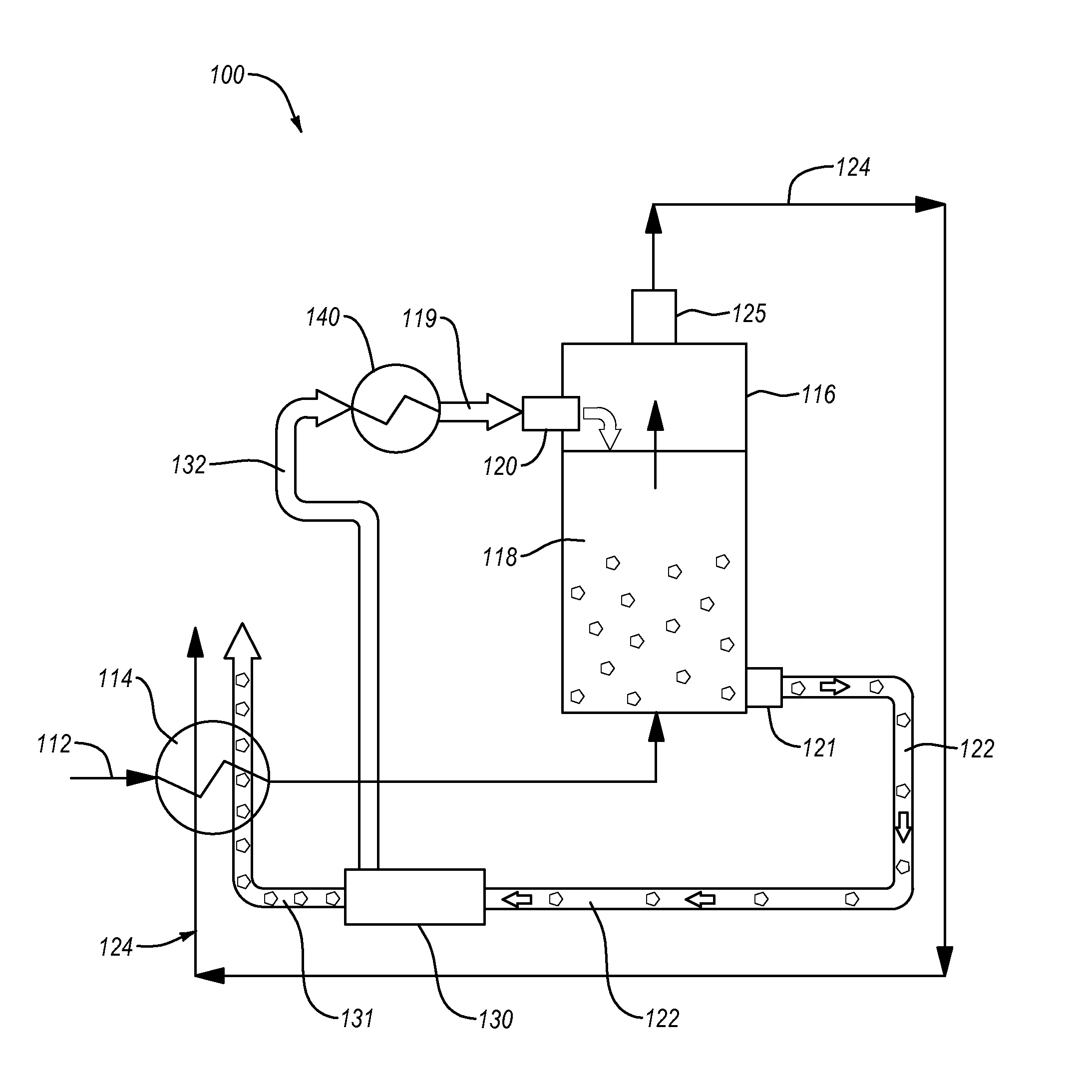
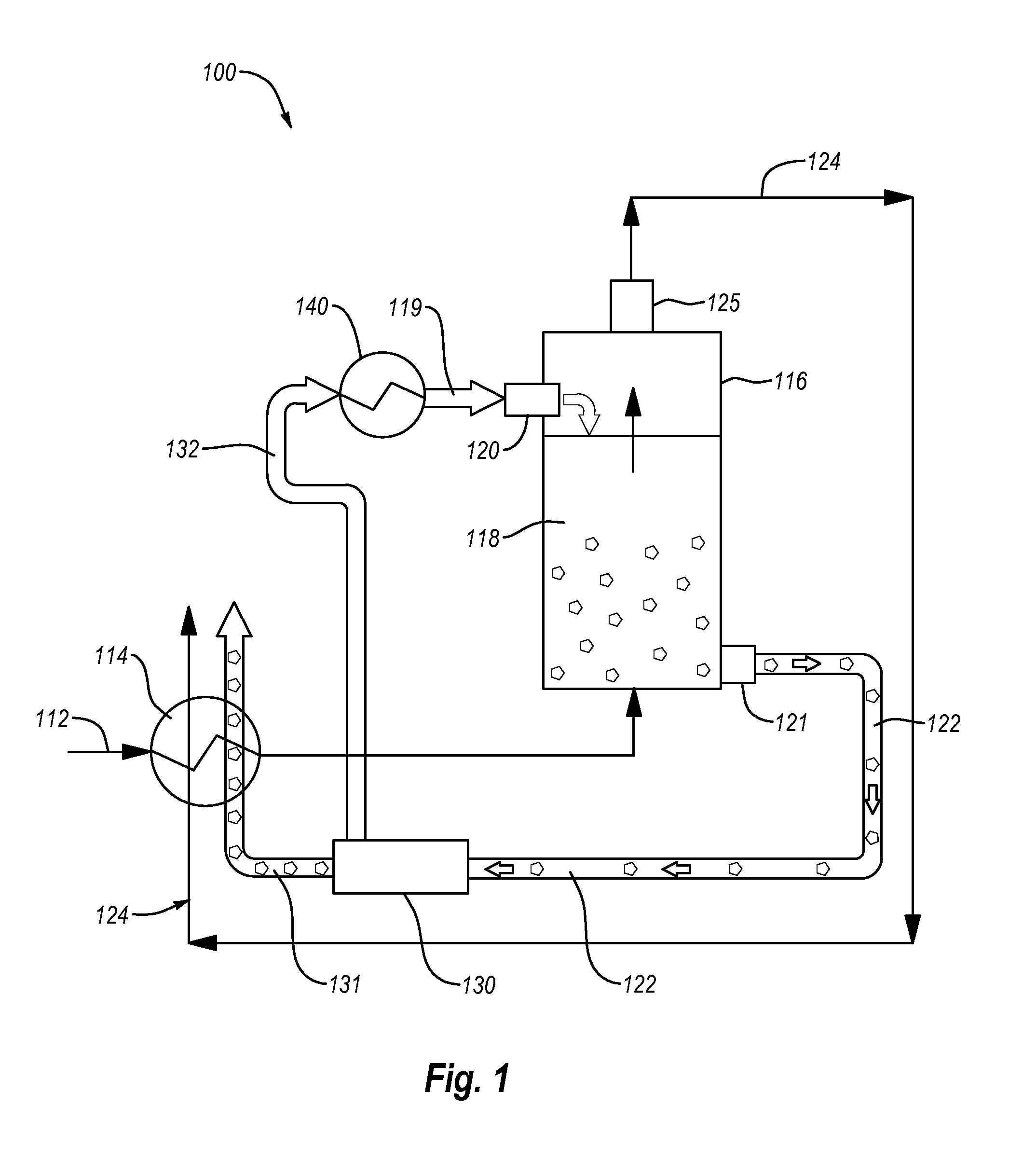
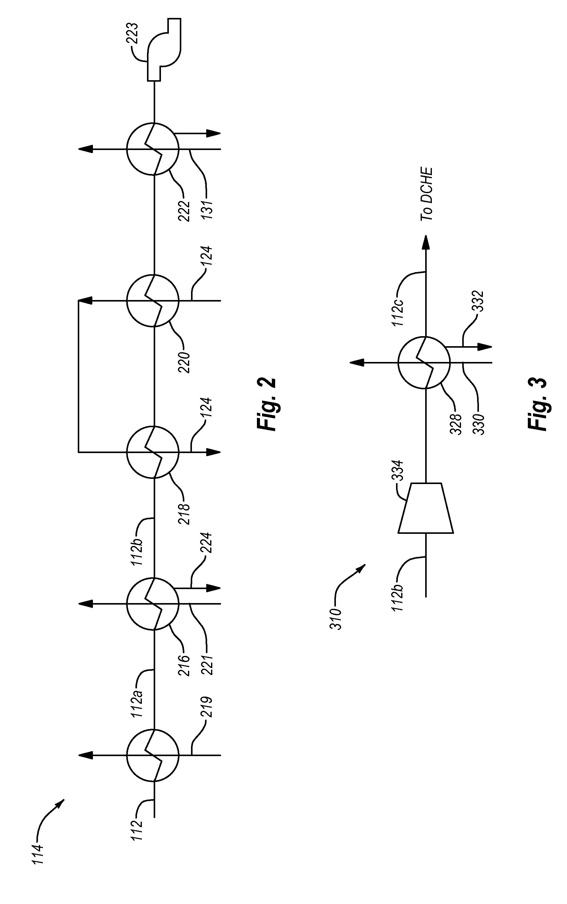
[0035]The systems and methods disclosed herein relate to separating condensable vapors from a process stream (e.g., the flue gas from a power plant) to form a solid and a separated light-gas stream. For example, in one embodiment, the methods and systems relate to condensing carbon dioxide vapors from a process stream that includes carbon dioxide and nitrogen. The systems and methods of the invention can be used to separate condensable vapors in any process stream that includes a mixture of gases, some of which can be readily caused to change phase. The process stream is typically produced in a hydrocarbon processing plant or sometimes in CO2 sensitive air supplies for life support. Examples of hydrocarbon processing plants and breathing air supply systems that produce a stream suitable for use in the present invention include, but are not limited to coal fired power plants, natural gas fired power plants, fuel oil fired power plants, biomass fired power plants, petrochemical proces...


PUM

PropertyMeasurementUnit
pressureaaaaaaaaaa
pressureaaaaaaaaaa
desublimation temperatureaaaaaaaaaa

Abstract

Condensable vapors such as carbon dioxide are separated from light gases in a process stream. The systems and methods employ a direct exchange heat exchanger to desublimate the condensable vapors from the process stream. The condensable vapors are condensed by directly contacting a heat exchange liquid in the direct contact heat exchanger while the uncondensed light gases from the process stream form a separated light-gas stream. The separated light-gas stream can be used in a recuperative heat exchanger to cool the process stream.

Description

CROSS-REFERENCE TO RELATED APPLICATIONS[0001]The present application claims the benefit of and priority to U.S. Provisional Patent Application Ser. No. 61 / 458,229 filed Nov. 19, 2010 and entitled METHOD FOR A DESUBLIMATING HEAT EXCHANGER, which is incorporated herein by reference in its entirety.BACKGROUND[0002]1. The Field of the Invention[0003]The present invention relates to systems and methods for separating condensable vapors (e.g., carbon dioxide) from gases by desublimating the condensable vapors in a heat exchange liquid.[0004]2. The Related Technology[0005]The separation of carbon dioxide from other light gases such as nitrogen is important for achieving carbon dioxide sequestration. Flue gas from a conventional power station typically includes from about 4% (vol.) to about 16% (vol.) carbon dioxide (CO2). It is commonly believed that this CO2 represents a significant factor in increasing the greenhouse effect and global warming. Therefore, there is a clear need for efficie...

Claims


Application Information

Patent Timeline
Patent Type & Authority Applications(United States)
IPC IPC(8): B01D53/00B01F3/04C01B32/55
CPCB01D7/02B01D53/002B01D2257/2045B01D2258/0283B01D2257/404B01D2257/504B01D2257/602B01D2257/302Y02P70/10
Inventor BAXTER, LARRY L.BENCE, CHRISTOPHER S.
Owner U S BANK TRUST CO NAT ASSOC
Why Eureka
Try Eureka