
Wear part with hard facing

a technology of hard facing and wear parts, applied in the direction of pretreatment surfaces, superimposed coating processes, coatings, etc., can solve the problems of high density and cost, degradation or melting of steel substrates, dense layer of mechanically keyed hard particles becoming attached to the surface, etc., and achieve the effect of sufficient robust handling and degree of flexibility

Active Publication Date: 2012-07-12
KONYASHIN IGOR YURI +2
View PDF4 Cites 9 Cited by
  • Summary
  • Abstract
  • Description
  • Claims
  • Application Information

AI Technical Summary

Benefits of technology

The invention provides a wear part or tool with a wear-resistant layer that is metallurgically bonded to an iron-group metal or alloy body through an intermediate layer. The wear-resistant layer contains a high amount of metal carbide grains, such as WC, TiC, and VC, and a metal based phase comprising an iron-group metal, silicon, and chromium. The wear-resistant layer is more resistant to wear and corrosion than the body of the tool. The method of producing the wear part or tool involves applying a layer of a composition containing metal carbide and components for the metal based phase to a surface of the body, raising the temperature of the layer and the surface to a level above the liquidus of the components, and allowing the components to solidify. The invention has particular application to wear parts with complex and non-planar surfaces.

Problems solved by technology

For example, cemented tungsten carbide is highly resistant to abrasion but due to its high density and cost is typically used only as the primary constituent of relatively small parts, such as drill bit inserts, chisels, cutting tips and the like.
The applied heat may result in the degradation or melting of a steel substrate.
In the spraying method, a powder comprising a hard phase, typically tungsten carbide, is caused to impact the wear part surface with high energy, resulting in a dense layer of mechanically keyed hard particles becoming attached to the surface.
If the coatings comprise WC—Co, it may be necessary to treat the coating at high temperatures exceeding about 1,350 deg. C. Such high temperatures may result in the distortion or melting of the steel substrate body, which is highly undesirable.
Another disadvantage of thermal spraying methods, such as flame, plasma or high velocity oxy-fuel (HVOF) spraying, is that they require expensive specialised equipment.
Unfortunately, this method is not practicable owing to the fact that the hard-metal shrinks during the sintering process, resulting in an inhomogeneous structure and severe cracking of the sintered layer (hard facing).
Another major problem is the need to apply high temperature to the layer and steel substrate.
Stainless steel alloys developed for the nuclear industry are taught in U.S. Pat. No. 5,660,939 and UK Patent No. 2,167,088, for example, and comprise chromium, nickel, silicon and carbon, but positively do not contain cobalt, which is generally unsuitable for use in a radio-active environment.
This long sintering time will result in considerable melting of both the binder components and the steel substrate.

Method used


Image

  • Wear part with hard facing
  • Wear part with hard facing
  • Wear part with hard facing

Examples


example 2

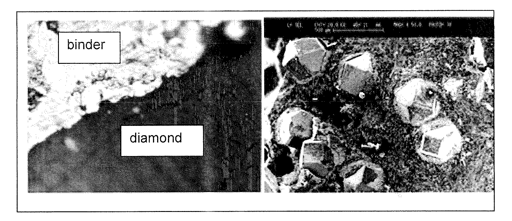
[0079]A 1 kg batch of powders comprising 67 wt. % WC powder with a mean diameter of about 0.8 μm, 24 wt. % Co powder, 6.4% Cr3C2 powder and 1.6 wt. % Si powder was milled for six hours in an attritor mill in a medium of hexane and 20 g paraffin wax and 6 kg hard-metal balls. After milling, the resulting slurry was dried and the powder was screened to eliminate agglomerates. Diamond grains with mean diameter in the range 300 to 400 um and having a TiC coating with average thickness about 0.5 um were introduced to the resulting powder at a level of 7 wt. %, and blended into the powder by means of a Turbular mixer. The weight percentage of diamond added was calculated to correspond to 20 vol. % diamond in the final sintered product. So, at this stage the mixture comprised 63 wt % WC, 22.5 wt. % Co, 7 wt. % diamond arains, 6 wt. % Cr3C2 and 1.5 wt. % Si.

[0080]The powder mixture was compacted by means of a conventional cold press to form cylindrically-shaped samples, which were sintered ...

example 3

[0082]A 1 kg batch of powders comprising 30 wt. % WC powder with a mean diameter of about 0.8 μm, 30 wt. % TiC, 20 wt. % Co powder, 10% Cr3C2 powder and 10 wt. % Si powder was milled for one hour in an attritor mill in a medium of hexane with 6 kg hard-metal balls. After milling, the resulting slurry was dried and the powder was screened to eliminate agglomerates. The resulting powder was mixed with 10% organic binder DECOFLUX® (Zschimmer & Schwarz). The paste obtained in such a way was applied onto the surface of steel substrates (carbon steel, ST50). The substrates with a layer of the paste were heat-treated in vacuum at a temperature of 1220 deg. C. for 2 min to form a continuous coating of roughly 3 mm in thickness on the steel substrate. The coated steel substrates were heat-treated by use of a conventional procedure for heat-treating steels.

[0083]The microstructure of the wear-resistant layer comprises facetted or rounded WC and TiC grains of 0.5 to 3.0 μm, rounded grains of (...

example 4

[0087]A paste was prepared comprising particles of 53 vol. % WC, 9 vol. % Cr3C2, 3 vol. % Si, 35 vol. % Co and an organic binder. The paste was applied to a portion of the steel body of a pick tool to form a layer with thickness in the range 2 to 3 mm and dried. Conventional brazing equipment was used to melt the paste in a non-oxidising atmosphere for about one minute at an applied temperature of about 1200 deg. C., above the melting point of the paste in the presence of iron at the interface with the steel substrate. The fact that conventional brazing equipment may be used to apply the hard facing is considered to be an important benefit of this method. The uncertainty in the temperature was about 30 deg. C, and it is believed that the applied temperature was about 1250 deg. C. The molten paste was found to be sufficiently viscous that it did not flow substantially during the brazing process. It is believed that the presence of Co in the paste enables brazing to be completed succe...


PUM

PropertyMeasurementUnit
thicknessaaaaaaaaaa
thicknessaaaaaaaaaa
thicknessaaaaaaaaaa

Abstract

The invention relates to a wear part or tool comprising a body containing an iron-group metal or alloy, a wear-resistant layer metallurgically bonded to a surface of the body through an intermediate layer, characterised in that the wear-resistant layer comprises at least 13 vol. % of grains of metal carbide selected from the group consisting of WC, TiC, VC, ZrC, NbC, Mo2C, HfC and TaC and grains of (Cr,Me)xCy and a metal based phase comprising of a solid solution of 0.5 to 20% Cr, 0.2 to 15% Si, and 0.2 to 20% carbon, where Me is Fe, Co and / or Ni; and the intermediate layer has a thickness of 0.05 to 1 mm and comprises Si in amount of 0.1 to 0.7 of that in the wear-resistant layer, chromium in amount of 0.1 to 0.6 of that in the wear-resistant layer and the metal of the metal carbide in amount of 0.2 to 0.6 of that in the wear-resistant layer and to a method of producing such a wear part.

Description

[0001]This application is a division of U.S. patent application Ser. No. 12 / 994,905 filed Feb. 15, 2011 entitled “Wear Part with Hard Facing” which is a 371 filing of International Application PCT / IB2009 / 054029 filed Sep. 15, 2009 which claims priority benefits to British Application 0816836.1 filed Sep. 15, 2008, all disclosures of which are herein incorporated by reference.INTRODUCTION[0002]This invention relates to the field of steel wear parts or tools, with metallurgically bonded hard facings. Such parts may be used in a wide variety of applications such as earth boring, excavating, oil and gas drilling and construction, cutting of stone, rock, metals, wood and composite materials, and chip-forming machining.BACKGROUND TO THE INVENTION[0003]Cemented carbide, also called hard-metal, is class of hard material comprising a hard phase of metal carbides and / or carbo-nitrides, the metal being selected from groups IVa to VIa of the periodic table and a metallic alloy binder comprising...

Claims


Application Information

Patent Timeline
Patent Type & Authority Applications(United States)
IPC IPC(8): B05D3/02
CPCC23C26/02C23C30/005C23C28/044Y10T428/12083Y10T428/12535Y10T428/12576Y10T428/12007C22C32/0052
Inventor KONYASHIN, IGOR YURIRIES, BERND HEINRICHLACHMANN, FRANK FRIEDRICH
Owner KONYASHIN IGOR YURI
Learn More