Particularly in urban or scenic areas, there is substantial resistance to allowing such towers to be built.
This
diameter limit in turn limits the thickness of the electrical insulation and thickness of the conductor in such a wire.
GIL, on the other hand, uses rigid conductor sections, and thus is not limited by the requirement of needing sufficient flexibility for the conductor to be coiled onto a transportable spool.
Although this technology can scale up to larger capacities and keep losses small by using large conductor sizes, the requirement to manage a pressurized gas along with the fact that SF6 is a very potent
greenhouse gas (22,800 times as bad as CO2 over 100 years, and thus suitable precautions must be taken to prevent accidental discharges), make this technology comparatively expensive.
It is a widely held belief within the
electric power industry that long distance transmission lines cannot be made out of short (15 meter, easily
truck-transportable sections) because the cumulative reliability for ˜130,000 splices×(λ130,000, where λ is the reliability of one splice over a given time) needed for a 1,000 km
transmission line would be unacceptably low.
Thus an unacceptable aggregate reliability is a problem with the splicing technology currently deployed for underground cables.
Any imperfections in this process [such as Contaminants, Protrusions, or Voids (referred to as CPV's in the industry) in excess of a few microns, whether the contaminants be conductive or insulative] can result in
premature failure by
electrical breakdown, per Advances in
High Voltage Engineering, page 494.
The whole existing process is labor intensive,
time consuming, and complex, and constitutes a weak point in
transmission system reliability even with only a small number of splices.
These methods are relatively complex and thus costly and a source of unreliability.
This can be caused by both changes in the
environmental temperature and the current (thus I2R loss) that the line is carrying.
Since this process inherently involves sliding
metal-to-
metal contact under pressure, wear will occur.
This wear will produce a conductive metallic dust.
In an HVDC GIL environment, the particles generated from sliding contactors and other sources can and do go back and forth between the conductor and the outer conduit as their charge changes each time they touch a
metal wall or conductor, and this allows the particles to bounce along and accumulate, which is particularly a problem only when GIL is deployed in an HVDC transmission mode.
Transporting large amounts of power, even at relatively high efficiency, results in the generation of a significant amount of
waste heat.
Larger capacities and larger loss levels result in proportionally larger amounts of
waste heat.
In fact, there can be different limitations for minimum
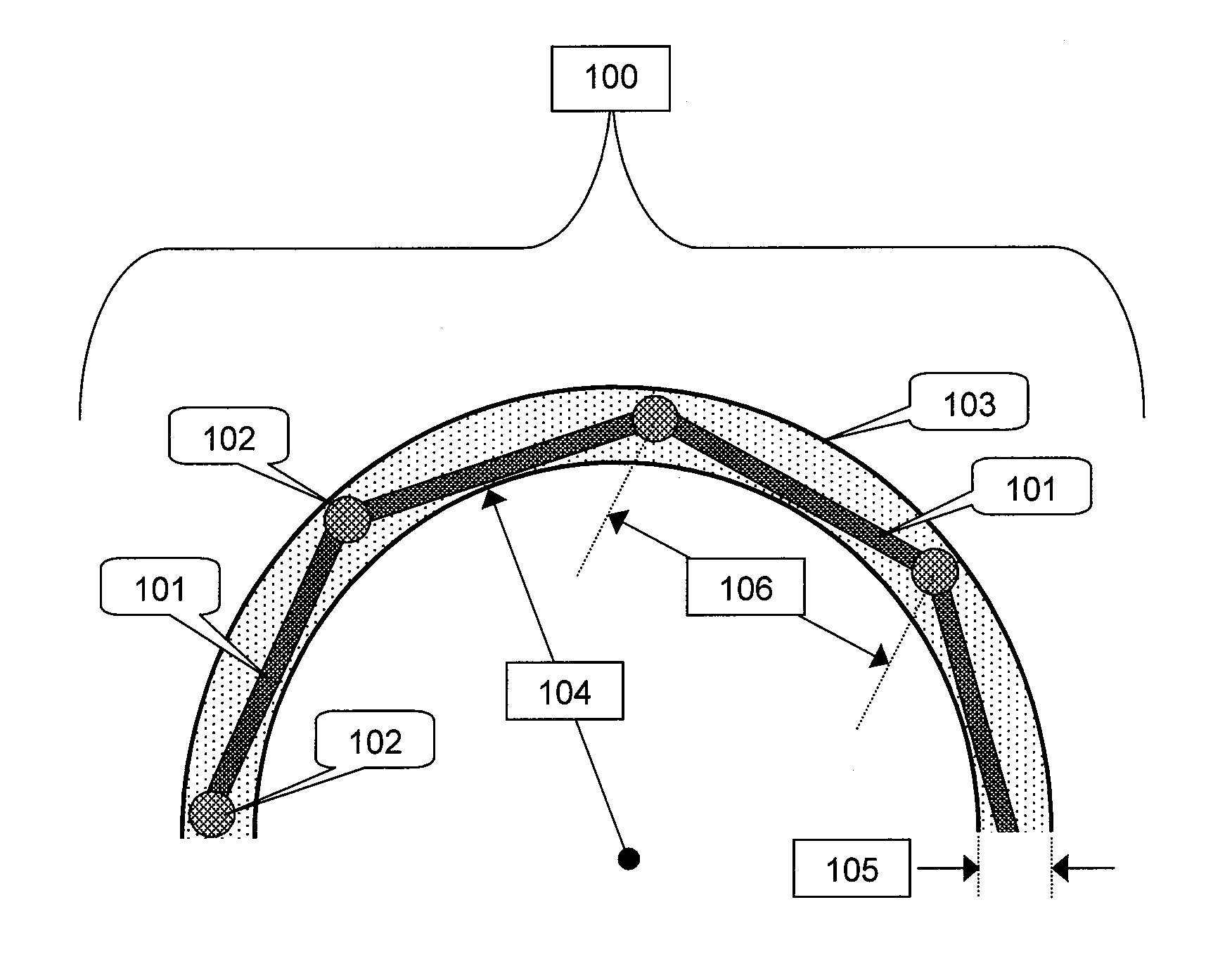
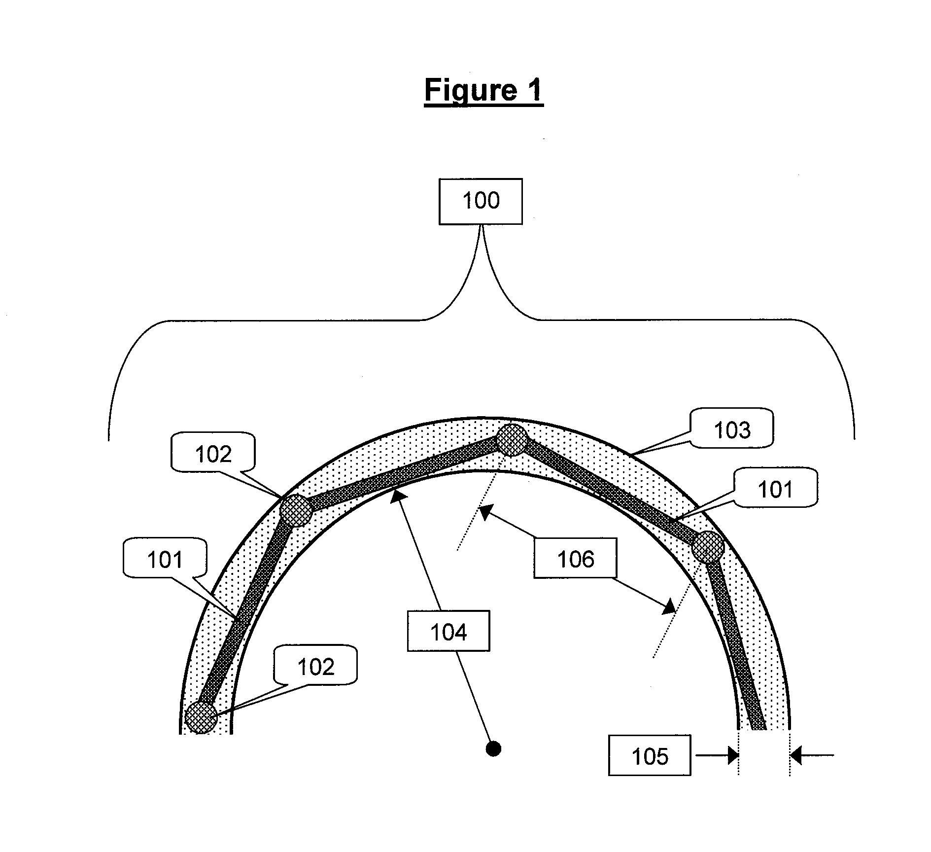
radius of curvature for shipping a conductor (where it is generally tightly wrapped on a reel for transport), compared to installation.
For example, large pipe-type cables may come on a 3 meter diameter cable reel, but they cannot be pulled through a conduit with less than about a 30 meter
radius of curvature.
If the insulation on a present technology cable fails during post-
manufacturing testing, the entire length of cable must be scrapped (though in some cases the conductor can be salvaged); contrast this with the case for the present elpipe segments, for which
high voltage testing is applied to the polymeric insulators before they are assembled into an elpipe segment, so that most failures in testing occur at the component level, rather than at the level of the segment module (where a failure is much more expensive).
There exists an optimum test
voltage for finding flaws in insulation; going above this optimum will damage the remaining insulation and decrease its service life, and testing at lower
voltage will fail to identify flaws that weaken the insulation substantially.
In present practice, since roughly kilometer-long segments of cable are manufactured at a time, testing aggressiveness is lower than would be feasible if the economic penalty for failure were less.
The basis for this statement is that failures are linked with flaws, and as higher test voltages are applied, smaller flaws can be detected.
It is not possible in strip-
casting to produce highly accurate and flexibly defined shapes, as can be done with
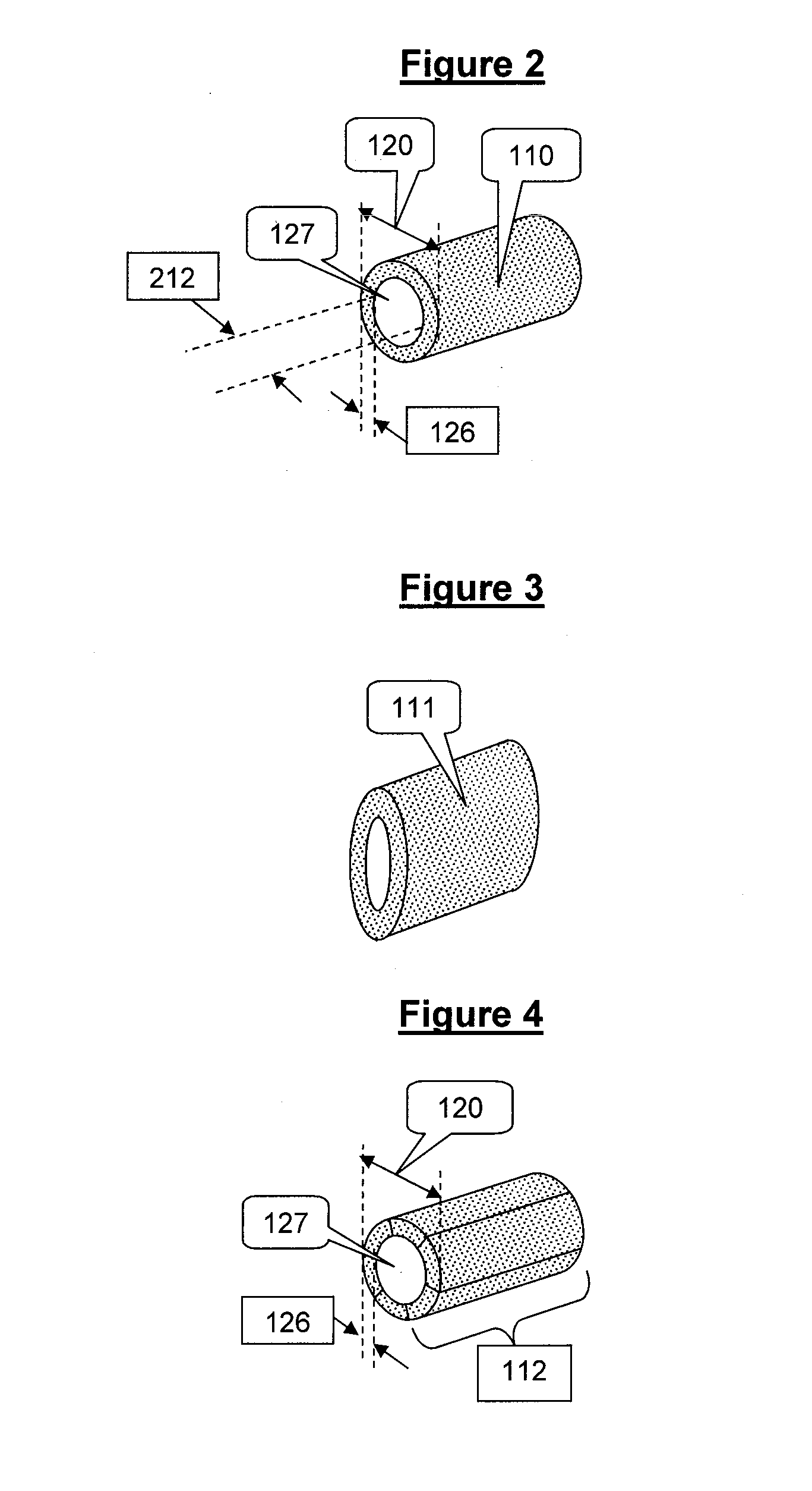
extrusion; however, strip cast shapes are less expensive than extruded shapes, and can be bundled together to produce a polygonal bundled conductor (FIG. 7).
If for example, one were to base a 12 GW elpipe on a 30 cm diameter extruded aluminum pipe, there are a small number of aluminum extruders worldwide who could extrude this pipe, which tends to increase the cost per
unit mass of the extruded product.
This shape however affords little opportunity for
fine tuning electrical resistance of the segment, as is desirable; one can either fill the inner cavity or not fill the inner cavity with
sodium, but doing a partial fill is risky because the
sodium could potentially melt in service, and
pool up at one end if the elpipe segment is installed on a slope.
Thus, pipe-shaped insulators made of stressed elastomers may not have greater thermal expansivity than the conductor, which is desirable.
Dynamically cured TPEs, such as Santoprene™, produced by Exxon Mobil of Houston, Tex., USA may be less useful than block
polymer based TPEs due
contamination by chemical residues of crosslinking.
One potential problem with using these plastics for the pipe-type insulators of elpipe segment modules is that in almost every case the thermal expansivity of
thermoplastic polymers is significantly higher than aluminum, creating a potential issue due to differential expansion of conductor versus insulator.
Unfortunately, these are not the best
polymer insulators.
Two other commercial processes could be used in principle, molding of sheet molding compound (SMC) or bulk molding compound (BMC), though most BMC and SMC molding compounds include reinforcing glass fibers and would not be suitable in a
high voltage gradient.
This method only works where the insulation has adequate compliance and / or well-matched
thermal coefficient of expansion (TCE) to the elpipe segment conductive core, which is difficult to achieve for hard plastics like crystalline syndiotactic
polystyrene.
This works by deliberately leaking some current to ground, and so the leakage current must not become so large as to significantly reduce the efficiency of the electric pipeline insulation.
This may not be possible to achieve exactly, since the change of resistivity in both Layer A and Layer B are non-linear, and the resistivity of Layer A may not be well controlled in the first place, possibly varying by an
order of magnitude from batch to batch.
Unfortunately, all feasible insulation materials experience major changes in resistivity over this temperature range.
This is enough to nearly equalize the
voltage gradient between subsequent spiral wraps, and is not enough to result in significant
energy loss from the line at near full capacity (resistance to ground over a 2000 km length of electric pipeline, considering both directions, is 15,500 ohms, compared to 1.15 ohms along the electric pipeline).
The same argument in favor of
modularity that was mentioned in regard to the desirability of separating the manufacture and testing of the pipe-shaped insulator from the pipe shaped conductor applies here as well: if the relatively inexpensive and preferably recyclable end cap insulator is formed separately, it can be exposed to more severe testing, therefore throwing out the largest flaws.
If this is done prior to
assembly with the far more expensive segment module conductor, the cost of failure is quite low.
In the normal method, QC records will show that a particular lot is especially good, but the acceptance tests were done only up to the specified minimum voltage, so these parts cannot be guaranteed to withstand a higher voltage than the tested voltage.
In comparing these two methods, snap-fit
assembly is faster, and far easier to certify for a 50-year life by QC methods than an
adhesive joint, which is intrinsically more complicated than a snap-fit joint to test and certify.
However, one cannot do the same thing with the inner surface of the elastomeric pipe-shaped insulator, though the inner surface of that tube can be somewhat more conductive than the bulk of the tube, though not enough so that the pipe-shaped insulator inner surface brings full voltage out to the end of the pipe-shaped insulator, which is sandwiched between the inner and outer end cap insulators.
Sodium can transport current more cheaply than aluminum, but is difficult to
handle and will likely be a concern to firefighters, safety professionals, and other individuals.
This method is likely more costly, with only modest improvement in performance projected, compared to the
oxide-inhibiting paste method described above.


