Permanent magnet and manufacturing method thereof

a permanent magnet and manufacturing method technology, applied in the field of permanent magnets, can solve problems such as defects such as poor heat resistance, and achieve the effects of avoiding serious deterioration of magnetic properties, reducing carbon content of magnet particles, and reducing coercive for

Inactive Publication Date: 2012-07-26
NITTO DENKO CORP
View PDF5 Cites 10 Cited by
  • Summary
  • Abstract
  • Description
  • Claims
  • Application Information

AI Technical Summary

Benefits of technology

[0023]According to the permanent magnet of the present invention having the above configuration, organic solvent is added in the wet-milling of a manufacturing process of the permanent magnet to the magnet powder, and by calcining a compact body of the organic-solvent-added magnet powder in hydrogen atmosphere before sintering, carbon content contained in magnet particles can be reduced previously. Consequently, the entirety of the magnet can be sintered densely without making a gap between a main phase and a grain boundary phase in the sintered magnet, and decline of coercive force can be avoided. Further, considerable alpha iron does not separate out in the main phase of the sintered magnet and serious deterioration of magnetic properties can be avoided.
[0024]Further, according to the permanent magnet of the present invention, V, Mo, Zr, Ta, Ti, W, or Nb can be efficiently concentrated in grain boundaries of the magnet. As a result, the grain growth during sintering can be inhibited, and at the same time, magnetization reversal of each magnet particle is prevented through disrupting exchange interaction among the magnet particles, enabling magnetic properties to be improved. Furthermore, as the additive amount of V, Mo, Zr, Ta, Ti, W, or Nb can be made smaller than that in a conventional method, the residual magnetic flux density can be inhibited from lowering.
[0025]According to the permanent magnet of the present invention having the above configuration, organic solvent is added in the wet-milling of a manufacturing process of the permanent magnet to the magnet powder, and by calcining the organic-solvent-added magnet powder in hydrogen atmosphere before sintering, carbon content contained in magnet particles can be reduced previously. Consequently, the entirety of the magnet can be sintered densely without making a gap between a main phase and a grain boundary phase in the sintered magnet, and decline of coercive force can be avoided. Further, considerable alpha iron does not separate out in the main phase of the sintered magnet and serious deterioration of magnetic properties can be avoided.
[0026]Further, according to the permanent magnet of the present invention, V, Mo, Zr, Ta, Ti, W, or Nb can be effectively concentrated in grain boundaries of the magnet. As a result, the grain growth during sintering can be inhibited, and at the same time, magnetization reversal of each magnet particle is prevented through disrupting exchange interaction among the magnet particles, enabling magnetic properties to be improved. Furthermore, as the additive amount of V, Mo, Zr, Ta, Ti, W, or Nb can be made smaller than that in a conventional method, the residual magnetic flux density can be inhibited from lowering.
[0027]Further, since powdery magnet particles are calcined, thermal decomposition of the organic compound can be caused more easily in the entirety of the magnet particles in comparison with the case of calcining compacted magnet particles. In other words, carbon content in the calcined body can be reduced more reliably.
[0028]Further, according to the permanent magnet of the present invention, V, Mo, Zr, Ta, Ti, W, or Nb, each of which is refractory metal, is concentrated in grain boundaries of the magnet. Therefore, V, Mo, Zr, Ta, Ti, W, or Nb concentrated in the grain boundaries prevents grain growth in the magnet particles at sintering, and at the same time disrupts exchange interaction among the magnet particles after sintering so as to prevent magnetization reversal in the magnet particles, making it possible to improve the magnetic performance thereof.

Problems solved by technology

On the other hand, as to Nd-based magnets such as Nd—Fe—B magnets, poor heat resistance is pointed to as defect.

Method used


Image

  • Permanent magnet and manufacturing method thereof
  • Permanent magnet and manufacturing method thereof
  • Permanent magnet and manufacturing method thereof

Examples


embodiment 1

[0106]In comparison with fraction regarding alloy composition of a neodymium magnet according to the stoichiometric composition (Nd: 26.7 wt %, Fe (electrolytic iron): 72.3 wt %, B: 1.0 wt %), proportion of Nd in that of the neodymium magnet powder for the embodiment 1 is set higher, such as Nd / Fe / B=32.7 / 65.96 / 1.34 in wt %, for instance. Further, 5 wt % of niobium ethoxide has been added as organometallic compound to the milled neodymium magnet powder. Further, toluene is used as organic solvent for wet milling. A calcination process has been performed by holding the magnet powder before compaction for five hours in hydrogen atmosphere at 600 degrees Celsius. The hydrogen feed rate during the calcination is 5 L / min. Sintering of the compacted-state calcined body has been performed in the SPS. Other processes are the same as the processes in [Second Method for Manufacturing Permanent Magnet] mentioned above.
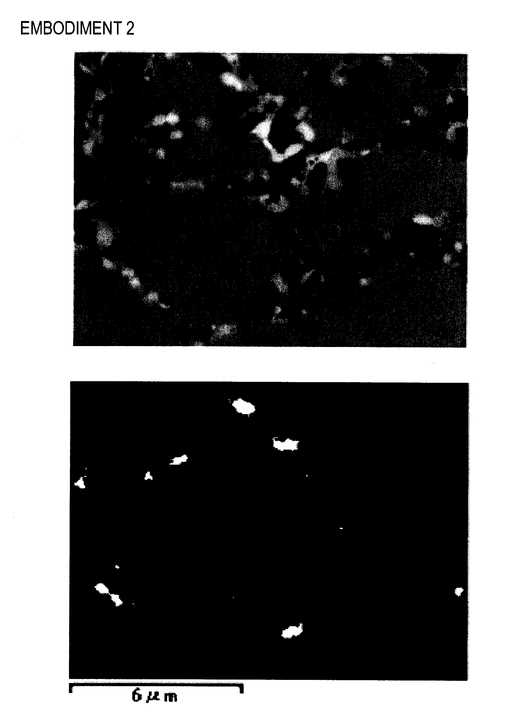
embodiment 2

[0107]Niobium n-propoxide has been used as organometallic compound to be added. Other conditions are the same as the conditions in embodiment 1.

embodiment 3

[0108]Niobium n-butoxide has been used as organometallic compound to be added. Other conditions are the same as the conditions in embodiment 1.


PUM

PropertyMeasurementUnit
particle sizeaaaaaaaaaa
thicknessaaaaaaaaaa

Abstract

There are provided a permanent magnet and a manufacturing method thereof enabling carbon content contained in magnet particles to be reduced in advance before sintering even when wet milling is employed. Coarsely-milled magnet powder is further milled by a bead mill in a solvent together with an organometallic compound expressed with a structural formula of M-(OR)X (M represents V, Mo, Zr, Ta Ti W or Nb, R represents a substituent group consisting of a straight-chain or branched-chain hydrocarbon, X represents an arbitrary integer) so as to uniformly adhere the organometallic compound to particle surfaces of the magnet powder. Thereafter, a compact body of compacted magnet powder is held for several hours in hydrogen atmosphere at 200 through 900 degrees Celsius to perform hydrogen calcination process. Thereafter, through sintering process, a permanent magnet 1 is formed.

Description

TECHNICAL FIELD[0001]The present invention relates to a permanent magnet and manufacturing method thereof.BACKGROUND ART[0002]In recent years, a decrease in size and weight, an increase in power output and an increase in efficiency have been required in a permanent magnet motor used in a hybrid car, a hard disk drive, or the like. To realize such a decrease in size and weight, an increase in power output and an increase in efficiency in the permanent magnet motor mentioned above, film-thinning and a further improvement in magnetic performance are required of a permanent magnet to be buried in the permanent magnet motor. Meanwhile, as permanent magnet, there have been known ferrite magnets, Sm—Co-based magnets, Nd—Fe—B-based magnets, Sm2Fe17Nx-based magnets or the like. As permanent magnet for permanent magnet motor, there are typically used Nd—Fe—B-based magnets due to remarkably high residual magnetic flux density.[0003]As method for manufacturing a permanent magnet, a powder sinte...

Claims


Application Information

Patent Timeline
Patent Type & Authority Applications(United States)
IPC IPC(8): H01F1/09B22F3/12H01F41/02B22F1/02
CPCB22F2998/00B22F2999/00H01F41/0266H01F1/086H01F1/0577H01F1/0572C22C2202/02C22C38/002C22C38/005B22F9/22B22F2201/013B22F9/04H01F1/053H01F1/08H01F41/02H02K15/03
Inventor OZEKI, IZUMIKUME, KATSUYAHIRANO, KEISUKEOMURE, TOMOHIROTAIHAKU, KEISUKEOZAKI, TAKASHI
Owner NITTO DENKO CORP
Why Eureka
Try Eureka