Fast switching for power inverter

a technology of power inverter and fast switching, which is applied in the direction of motor/generator/converter stopper, dynamo-electric converter control, pulse technique, etc., to achieve the effect of reducing excessive voltage overshoot and reducing the risk of occurren

Active Publication Date: 2012-08-02
TESLA INC
View PDF25 Cites 19 Cited by
  • Summary
  • Abstract
  • Description
  • Claims
  • Application Information

AI Technical Summary

Benefits of technology

[0011]Disclosed is a system and method for dynamic control of a gate drive negative rail voltage to efficiently and economically reduce excessive voltage overshoot. An apparatus includes an inverter including a high-side switch coupled to a low-side switch, the inverter generating a time-varying drive current from a plurality of drive control signals, a positive rail voltage, and a negative rail voltage wherein controlling the switches to generate the time-varying drive current produces a potential transitory overshoot condition for one of the switches of the inverter; a drive control, coupled to the inverter, to generate the drive control signals and to set a level of each of the rail voltages responsive to a plurality of controller signals; and a controller monitoring one or more parameters indicative of the potential transitory voltage overshoot condition, the controller dynamically adjusting, responsive to the monitored parameters, the controller signals to reduce a risk of occurrence of the potential transitory voltage overshoot condition.

Problems solved by technology

Device datasheets do not contain definitive parameters or data showing this effect, partially since device overshoot is a strong function of the parasitic inductance in the system surrounding the devices.

Method used


Image

  • Fast switching for power inverter
  • Fast switching for power inverter
  • Fast switching for power inverter

Examples


Embodiment Construction

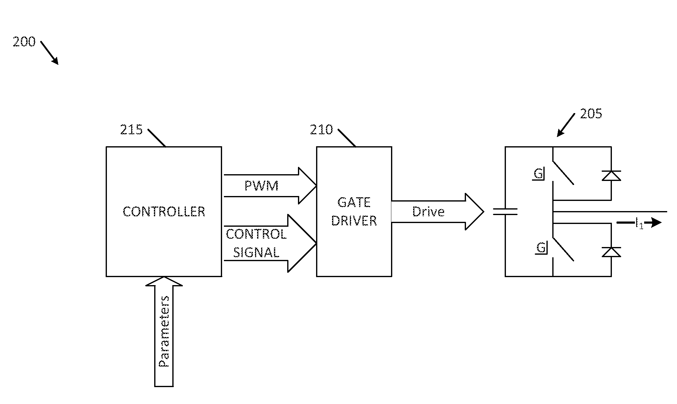
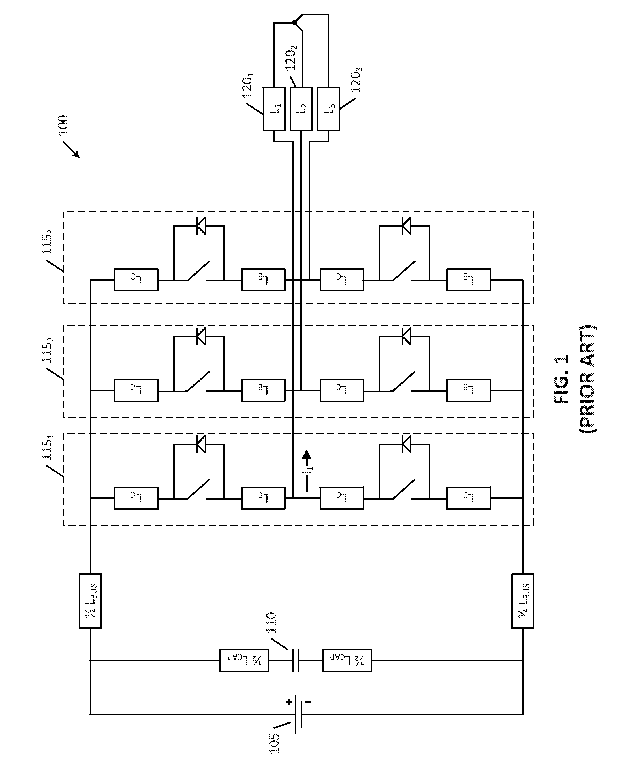
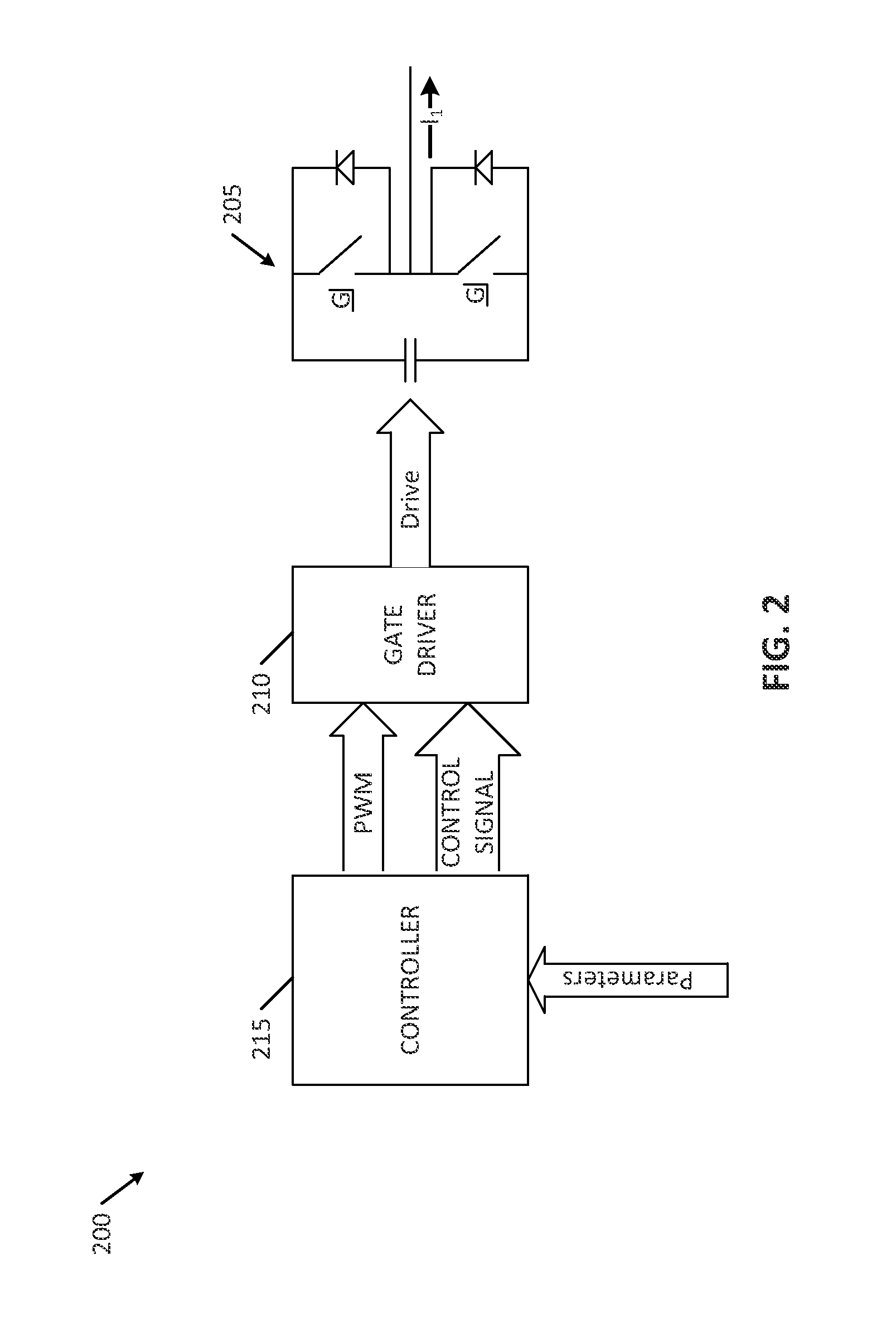
[0029]Embodiments of the present invention provide methods and systems for a system and method for dynamic control of a gate drive negative voltage rail to efficiently and economically reduce excessive voltage overshoot. The following description is presented to enable one of ordinary skill in the art to make and use the invention and is provided in the context of a patent application and its requirements. In the following text, the terms “energy storage assembly,”“battery,”“cell,”“battery cell,”“battery cell pack,”“electrolytic double-layer capacitor,” and “ultracapacitor” may be used interchangeably (unless the context indicates otherwise” and may refer to any of a variety of different rechargeable configurations and cell chemistries including, but not limited to, lithium ion (e.g., lithium iron phosphate, lithium cobalt oxide, other lithium metal oxides, etc.), lithium ion polymer, nickel metal hydride, nickel cadmium, nickel hydrogen, nickel zinc, silver zinc, or other chargeabl...


PUM


Abstract

An apparatus includes an inverter including a high-side switch coupled to a low-side switch, the inverter generating a time-varying drive current from a plurality of drive control signals, a positive rail voltage, and a negative rail voltage wherein controlling the switches to generate the time-varying drive current produces a potential transitory overshoot condition for one of the switches of the inverter; a drive control, coupled to the inverter, to generate the drive control signals and to set a level of each of the rail voltages responsive to a plurality of controller signals; and a controller monitoring one or more parameters indicative of the potential transitory voltage overshoot condition, the controller dynamically adjusting, responsive to the monitored parameters, the controller signals to reduce a risk of occurrence of the potential transitory voltage overshoot condition.

Description

CROSS REFERENCE TO RELATED APPLICATIONS[0001]The present application is a continuation of U.S. patent application Ser. No. ______ (Atty Docket 20109-7022), and related to U.S. patent application Ser. No. ______ (Atty Docket 20109-7037), and U.S. patent application Ser. No. ______ (Atty Docket 20109-7038), all filed on the same date with the same title. The contents and disclosures of all these applications are hereby expressly incorporated in their entireties by reference thereto for all purposes.BACKGROUND OF THE INVENTION[0002]The present invention relates generally to switching of semiconductor power devices, and more specifically to selectively decreasing excessive voltage overshoot during fast turn-off of hard-switched high voltage semiconductor power devices.[0003]There are many applications for high-speed switching of semiconductor power devices. Some applications are referred to as soft-switched (whether active or passive) and some are referred to as hard-switched. Hard-swit...

Claims


Application Information

Patent Timeline
Patent Type & Authority Applications(United States)
IPC IPC(8): H02P27/06H02H7/122
CPCH02M1/32H02M7/538H03K17/166H03K17/0822H02P27/06
Inventor KROEZE, RYANCAMPBELL, COLINKALAYJIAN, NICHOLAS R.
Owner TESLA INC
Why Eureka
Try Eureka