

Polymer electrolyte membrane for a fuel cell, and method for preparing same
a fuel cell and electrolyte technology, applied in the direction of fuel cell details, electrochemical generators, capacitors, etc., can solve the problems of increasing the consumption of raw materials, not only ohmic loss, but also ohmic loss, etc., to improve proton conductivity, improve the overall thickness of the electrolyte membrane, and improve the mechanical strength
Active Publication Date: 2012-09-13
KOLON IND INC
View PDF0 Cites 29 Cited by
- Summary
- Abstract
- Description
- Claims
- Application Information
AI Technical Summary
Benefits of technology
[0027]First, the polymer electrolyte membrane according to the present invention has a structure of ionomers charged in pores of the nanoweb, which has excellent thermal resistance and is insoluble in an organic solvent, under optimum conditions. Therefore, an overall thickness of the electrolyte membrane may be reduced, thus improving proton conductivity while reducing ohmic loss and reducing thickness expansion rate. Consequently, performance of the foregoing membrane may be successfully retained for a long period of time.
[0028]Second, the polymer electrolyte membrane of the present invention may include a nanoweb and an ionomer, both of which comprise hydrocarbon polymer materials to improve adhesion therebetween, thereby attaining excellent durability.
[0029]Third, the polymer electrolyte membrane of the present invention is prepared using hydrocarbon polymer materials at relatively low cost, without using conventional fluorine-based ionomers or Teflon resin. Consequently, the present invention is economical preferably in terms of cost and mass production.
Problems solved by technology
However, the fluorine ionomer has a low mechanical strength and, when used for a long period of time, pinholes may be generated which in turn causes deterioration in energy conversion efficiency.
Although increasing a membrane thickness of the fluorine ionomer has been attempted to reinforce mechanical strength, this increases not only ohmic loss but also consumption of an expensive raw material, thus being less economical.
However, since the Teflon resin has very low adhesiveness, selection of ionomers is restricted.
In addition, a fluorine ionomer-applied product entails a disadvantage of high crossover (phenomenon), compared to hydrocarbon based products.
Further, since the porous Teflon resin as well as the fluorine ionomer are expensive, development of cheap and novel materials for mass-production is still required.
Method used
View moreImage
Smart ImageViewing Examples

Examples
example 2
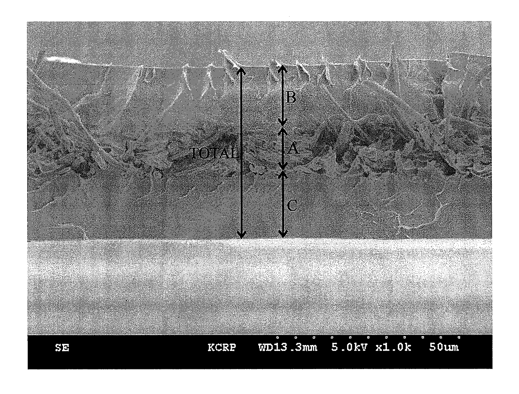
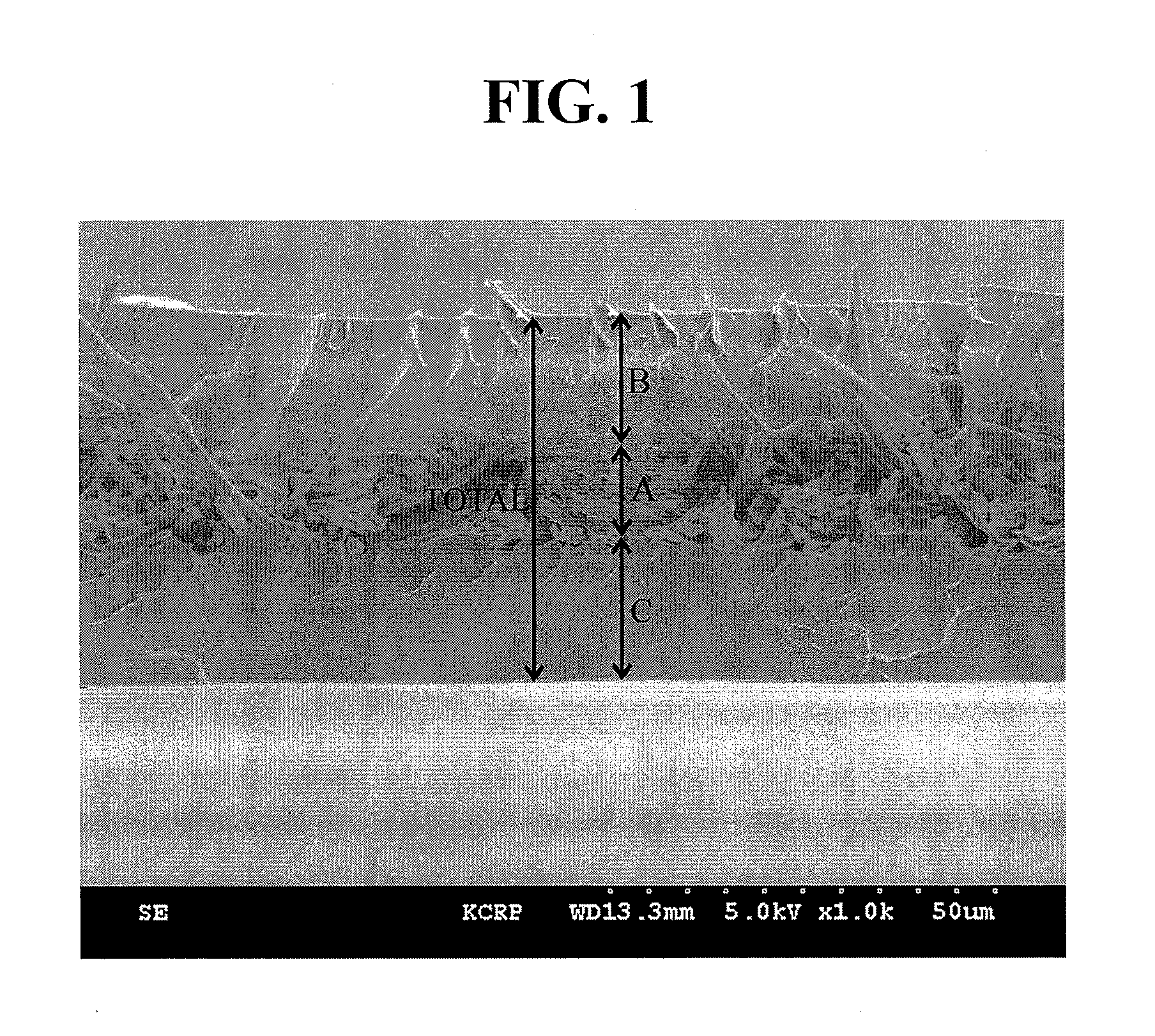
[0080]A polymer electrolyte membrane was produced by the same procedure as described in Example 1, except that the average diameter of the porous nanoweb was changed to 10 μm by controlling electrical spinning conditions and the average thickness of an electrolyte film was changed to 50 μm by adjusting an immersed amount of the ionomer.
Login to View More PUM
| Property | Measurement | Unit |
|---|---|---|
| diameter | aaaaa | aaaaa |
| thickness | aaaaa | aaaaa |
| pore diameter | aaaaa | aaaaa |
Abstract
The present disclosure relates to a polymer electrolyte membrane having a construction wherein an ionomer is charged in pores of a nanoweb having a high melting point, being insoluble in an organic solvent and having excellent pore characteristics, under optimum conditions. Therefore, an overall thickness of the electrolyte membrane may be reduced, thereby attaining advantages such as decrease in ohmic loss, reduction of material costs, excellent heat resistance, low thickness expansion rate which in turn prevents proton conductivity from being deteriorated over a long term. The polymer electrolyte membrane of the present invention comprises a porous nanoweb having a melting point of 300□ or more and being insoluble in an organic solvent of NMP, DMF, DMA, or DMSO at room temperature; and an ionomer which is charged in pores of the porous nanoweb and contains a hydrocarbon material soluble in the organic solvent at room temperature.
Description
TECHNICAL FIELD[0001]The present invention relates to an electrolyte membrane for a fuel cell and, more particularly, to a polymer electrolyte membrane.BACKGROUND ART[0002]A fuel cell refers to a battery directly changing chemical energy generated by oxidation of a fuel into electric energy (that is, electricity) and has high energy efficiency and eco-friendly features such as reduced discharge of contaminants, thereby becoming popular as a next-generation energy source.[0003]The fuel cell generally has a structure comprised of an oxidation electrode (anode) and a reduction electrode (cathode) by interposing an electrolyte membrane, and such a structure is referred to as a membrane electrode assembly (MEA).[0004]The fuel cell may include an alkali electrolyte membrane fuel cell, a polymer electrolyte membrane fuel cell (PEMFC), etc., in terms of types of electrolytes, and among these, the polymer electrolyte membrane fuel cell shows advantageous features such as low operational temp...
Claims
Login to View More Application Information
Patent Timeline
 Patent Type & AuthorityApplications(United States)
IPC IPC(8): H01M8/10B82Y30/00
CPCC08J2339/06C08J2381/02C08J5/2275H01B1/122H01M8/0293Y02E60/521H01M8/103H01M8/1032H01M8/106H01M8/1062H01M2300/0088H01M8/1027Y02E60/50
InventorLEE, MOO-SEOKSHIN, YONG-CHEOLRYU, JAE HEEKIM, NA YOUNGKIM, KYOUNG-JUKIM, CHUL KILEE, YONG-HWANKANG, YUN KYUNG
OwnerKOLON IND INC