Flexible conductive material and transducer, flexible wiring board, and electromagnetic shield using the same

a technology of flexible conductive material and transducer, which is applied in the direction of conductive layers on insulating supports, non-metal conductors, conductors, etc., can solve the influence of impurities contained in the member touching the flexible conductive material, power consumption increases, and the dielectric film is more likely to break, so as to reduce the electric resistance of the touching member

Active Publication Date: 2012-09-27
SUMITOMO RIKO CO LTD
View PDF5 Cites 17 Cited by
  • Summary
  • Abstract
  • Description
  • Claims
  • Application Information

AI Technical Summary

Benefits of technology

[0022]The flexible conductive material of the present invention can be manufactured from a coating material in which a raw material such as a rubber polymer is dissolved in a predetermined solvent. Alternatively, the flexible conductive material of the present invention can be formed in various shapes from a kneaded raw material. Therefore, the flexible conductive material of the present invention is easily disposed as an electromagnetic shield in various positions where shielding from electromagnetic waves is desi

Problems solved by technology

Thus, the influence of impurities contained in the member touching the flexible conductive material cannot be ignored.
Accordingly, electric charge is unlikely to be stored at an interface between the dielectric film and the electrode, and power consumption increases

Method used


Image

  • Flexible conductive material and transducer, flexible wiring board, and electromagnetic shield using the same
  • Flexible conductive material and transducer, flexible wiring board, and electromagnetic shield using the same
  • Flexible conductive material and transducer, flexible wiring board, and electromagnetic shield using the same

Examples


first embodiment

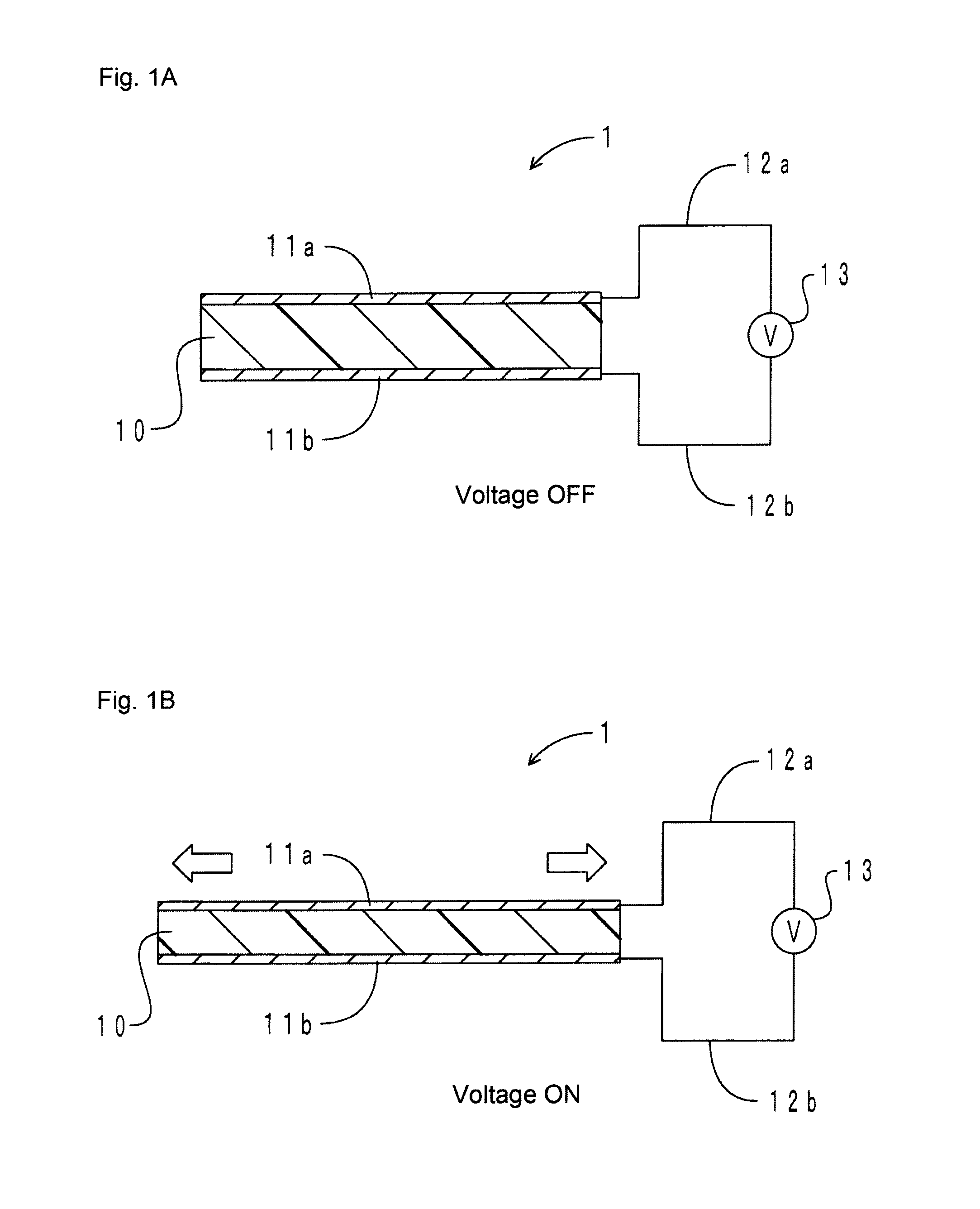
[0057]As a first example of the transducer of the present invention, an embodiment of an actuator is described. FIGS. 1A and 1B show cross-sectional schematic diagrams of the actuator in the present embodiment. FIG. 1A shows a voltage OFF state and FIG. 1B shows a voltage ON state.

[0058]As shown in FIGS. 1A and 1B, an actuator 1 is provided with a dielectric film 10, electrodes 11a and 11b, and wirings 12a and 12b. The dielectric film 10 is made of H-NBR. The electrode 11a is disposed so as to cover approximately the entire upper surface of the dielectric film 10. Similarly, the electrode 11b is disposed so as to cover approximately the entire lower surface of the dielectric film 10. The electrodes 11a and 11b are connected to a power source 13 by the wirings 12a and 12b, respectively. The electrodes 11a and 11b are both configured with the flexible conductive material of the present invention.

[0059]When switching from the OFF state to the ON state, voltage is applied between the pa...

second embodiment

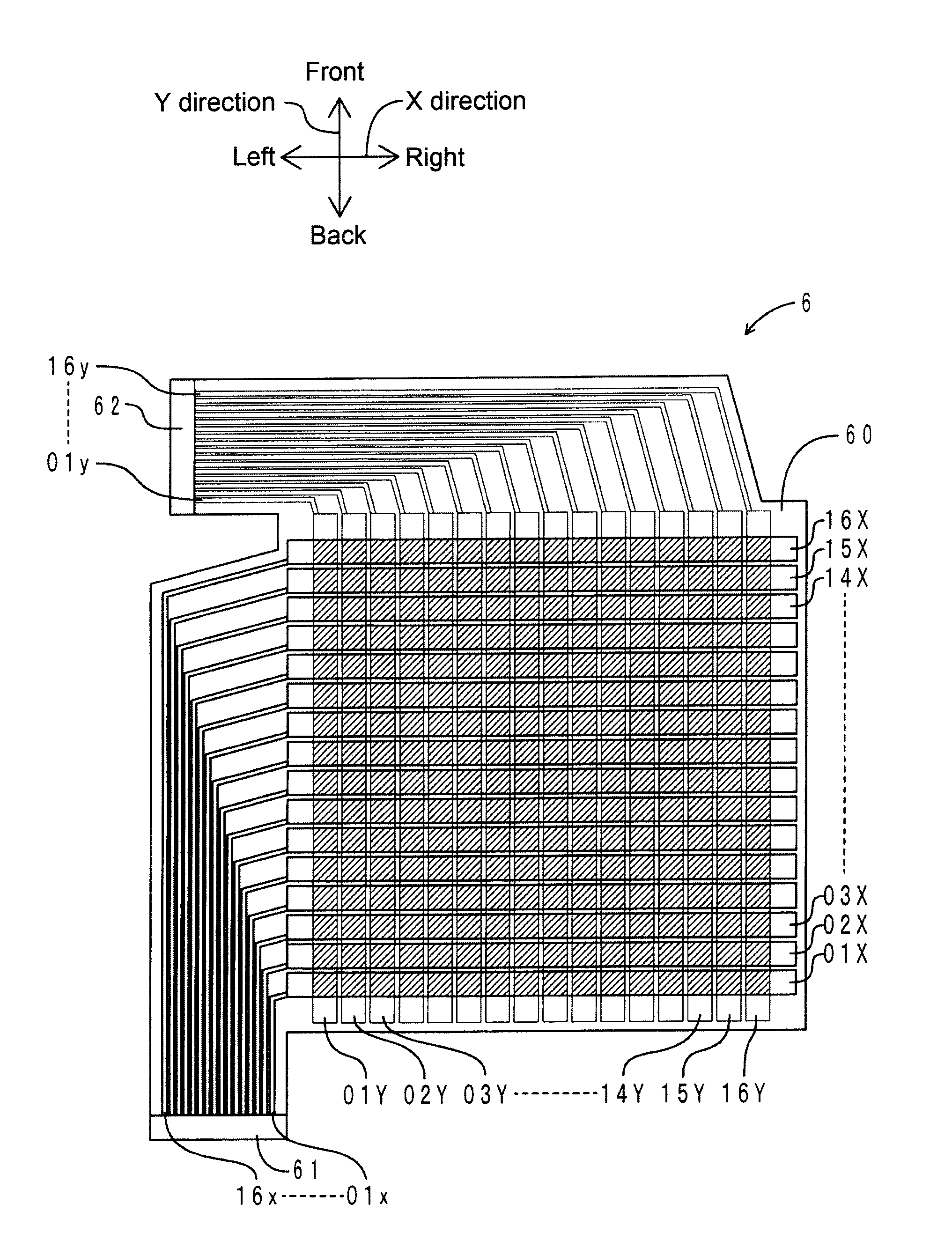
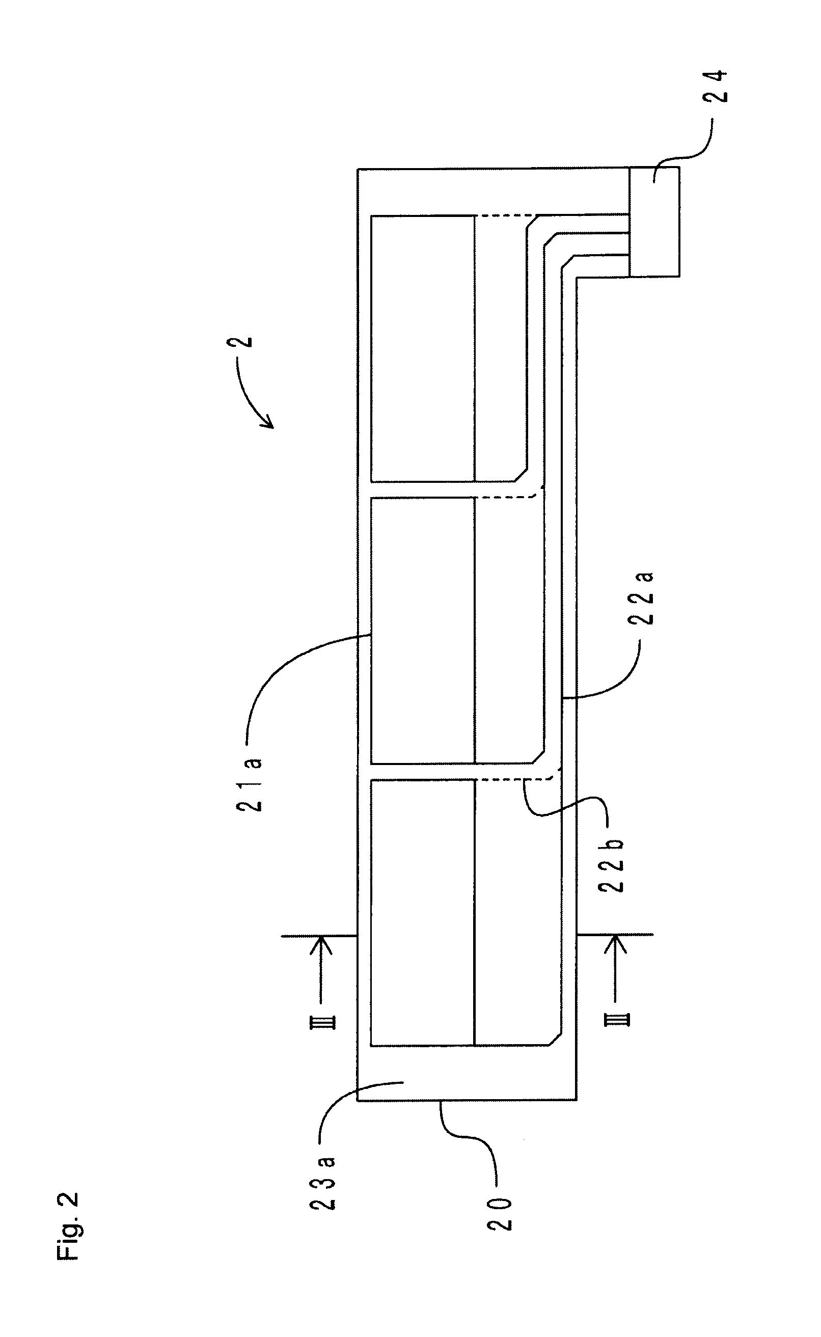
[0065]As a second example of the transducer of the present invention, an embodiment of a capacitance-type sensor is described. First, the configuration of the capacitance-type sensor of the present embodiment is described. FIG. 2 is a top view of the capacitance-type sensor. FIG. 3 is a cross-sectional view along a line III-III in FIG. 2. As shown in FIGS. 2 and 3, a capacitance-type sensor 2 is provided with a dielectric film 20, a pair of electrodes 21a and 21b, wirings 22a and 22b, and cover films 23a and 23b.

[0066]The dielectric film 20 is made of H-NBR and has a belt shape extending in a left-right direction. The thickness of the dielectric film 20 is approximately 300 μm.

[0067]The electrode 21a has a rectangular shape. Three electrodes 21a are formed by screen printing on an upper surface of the dielectric film 20. Similarly, the electrode 21b has a rectangular shape. Three electrodes 21b are formed on a lower surface of the dielectric film 20 so as to oppose the electrodes 2...

third embodiment

[0073]As a third example of the transducer of the present invention, an embodiment of a power generating element is described. FIGS. 4A and 4B are cross-sectional schematic diagrams of the power generating element in the present embodiment. FIG. 4A shows the power generating element during extension and FIG. 4B shows the power generating element during contraction.

[0074]As shown in FIGS. 4A and 4B, a power generating element 3 is provided with a dielectric film 30, electrodes 31a and 31b, and wirings 32a to 32c. The dielectric film 30 is made of H-NBR. The electrode 31a is disposed so as to cover approximately an entire upper surface of the dielectric film 30. Similarly, the electrode 31b is disposed so as to cover approximately an entire lower surface of the dielectric film 30. The electrode 31a is connected to the wirings 32a and 32b. Specifically, the electrode 31a is connected to an external load (not pictured) via the wiring 32a. Also, the electrode 31a is connected to a power ...


PUM

PropertyMeasurementUnit
Temperatureaaaaaaaaaa
Timeaaaaaaaaaa
Fractionaaaaaaaaaa

Abstract

A flexible conductive material includes an elastomer, a conductive agent filled in the elastomer, and an adsorbent fixed inside the elastomer and able to adsorb ionic material. With the flexible conductive material, ionized impurities are unlikely to transfer to an adherend such as a dielectric film. Thus, leakage current during application of voltage decreases. Accordingly, by forming an electrode and a wiring with the flexible conductive material, leakage current can be reduced, and a transducer and a flexible wiring board having excellent durability can be produced. In addition, using the flexible conductive material, an electromagnetic shield can be produced having a small leakage current.

Description

CLAIM OF PRIORITY[0001]This application is a continuation of PCT / JP2011 / 073423 filed Oct. 12, 2011, and claims the priority benefit of Japanese Applications No. 2010-230614, filed Oct. 13, 2010, and No. 2011-051365, filed Mar. 9, 2011, the contents of which is expressly incorporated by reference in its entirety.FIELD OF THE INVENTION[0002]The present invention relates to a flexible conductive material which is favorable for an extendable and contractible electrode, a wiring, and the like, and to a transducer, a flexible wiring board, and an electromagnetic shield using the same.BACKGROUND OF THE INVENTION[0003]Using a polymer material such as a dielectric elastomer, development has advanced for small, light-weight transducers having a high degree of flexibility. Examples of a transducer include an actuator in which a pair of electrodes is disposed on both a front and back surface of a dielectric film made from an elastomer (see, for example, Patent Documents 1 and 2). In an actuator...

Claims


Application Information

Patent Timeline
IPC IPC(8): H01B1/20H01B1/22H05K9/00H01B1/24H02N11/00H05K1/02
CPCH01B1/22H01B1/24H05K1/0256H05K1/0373H05K1/162C08K3/04H05K2201/0133H05K2201/0323C08L15/005H10N30/878H10N30/206H10N30/30H10N30/857H01B1/20H01B5/14H02N1/00H01R11/01H10N30/1051
Inventor ITOU, TAKAMASAKOBAYASHI, JUNYOSHIKAWA, HITOSHI
Owner SUMITOMO RIKO CO LTD
Why Eureka
Try Eureka