High dielectric constant composite materials and methods of manufacture

a composite material, high dielectric constant technology, applied in the field of composite materials, can solve the problems of low dielectric strength limiting the application of high voltage, high power, or high energy storage systems, and reducing the dielectric constant of conventional ceramic materials, so as to achieve high dielectric constant and increase the dielectric strength of composite materials. , the effect of high dielectric constan

Active Publication Date: 2012-09-27
UNIVERSITY OF MISSOURI
View PDF4 Cites 57 Cited by
  • Summary
  • Abstract
  • Description
  • Claims
  • Application Information

AI Technical Summary

Benefits of technology

[0014]After polymerization or other formation of the polymer binder, the dielectric fluid is impregnated into the composite material to fill or displace any voids remaining in the composite material, thereby increasing both the dielectric constant and the dielectric strength of the composite material. The composite material may be submerged and/or bathed in the dielectric fluid. Alternately, the dielectric fluid may be forced into the pores of the ceramic material using a vacuum or other pressurized system.
[0015]A method for manufacturing a composite material having a high dielectric constant includes mixing a ceramic powder having a distribution of ceramic particles with

Problems solved by technology

Conventional ceramic materials, however, are typically brittle and susceptible to fracturing under tensile and torsion stresses.
Additionally, conventional ceramic materials exhibit a low dielectric strength, limiting their application in high voltage, high power, or high energy storage systems.
Ex

Method used


Image

  • High dielectric constant composite materials and methods of manufacture
  • High dielectric constant composite materials and methods of manufacture
  • High dielectric constant composite materials and methods of manufacture

Examples


example 1

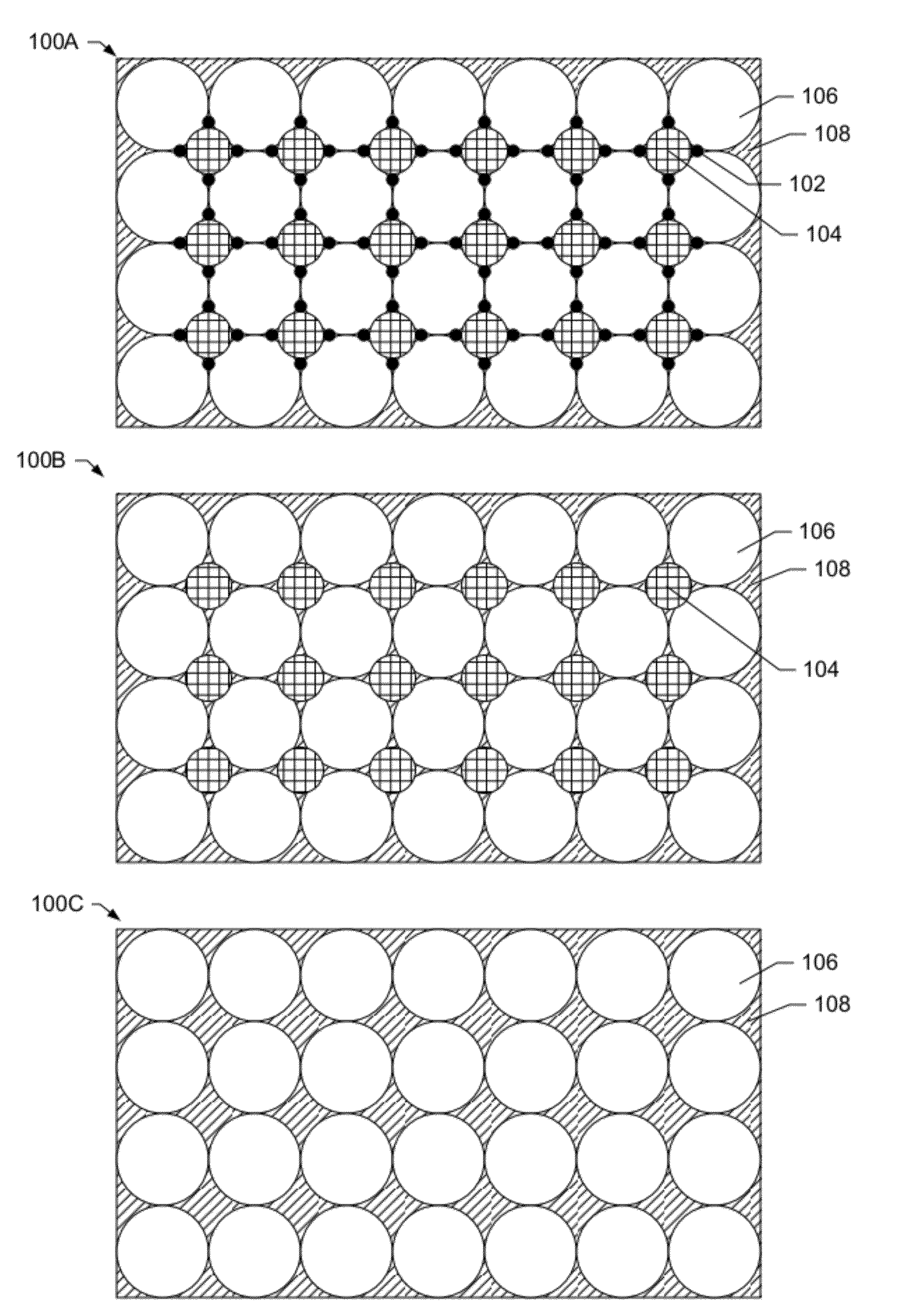
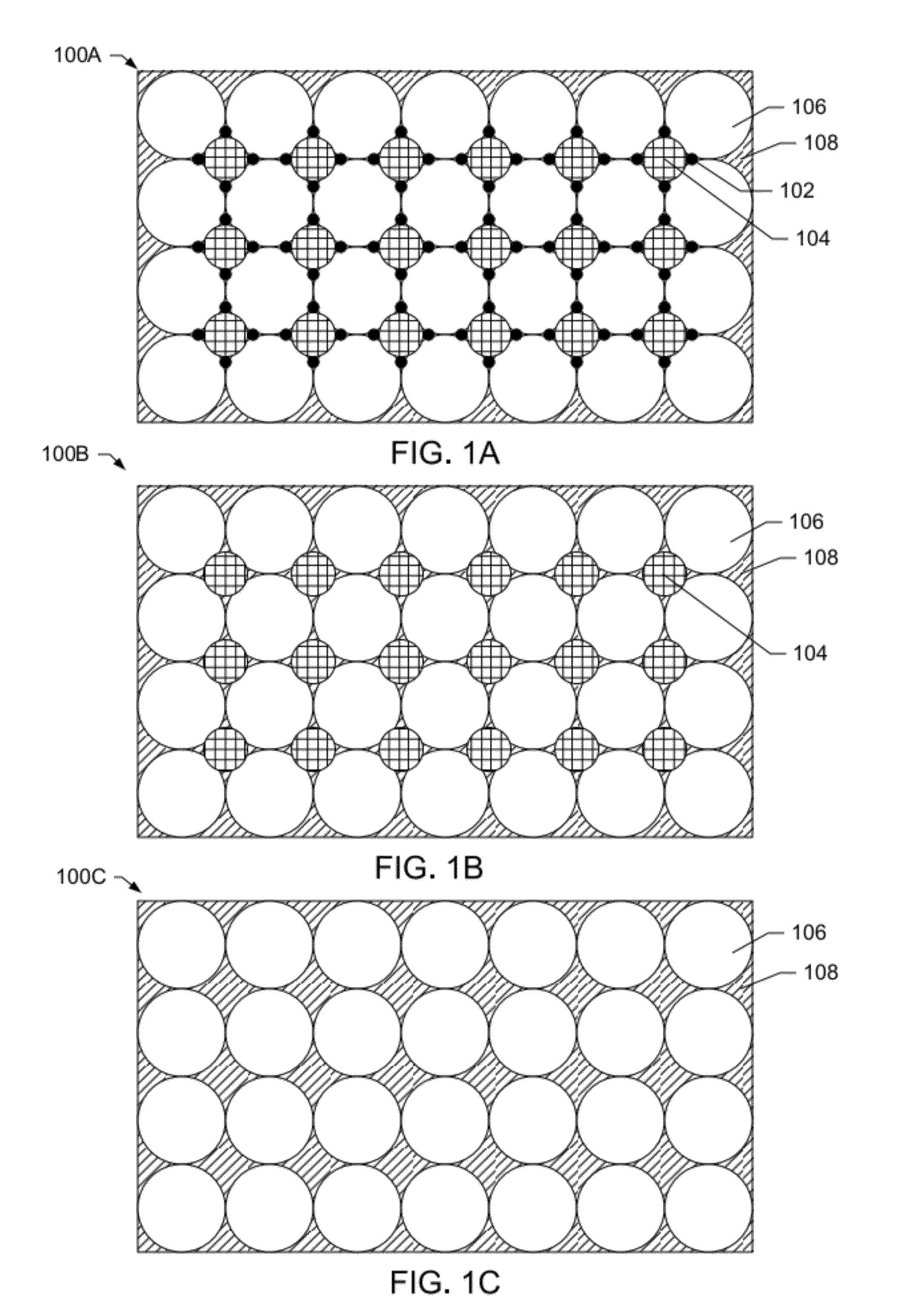
[0081]By way of example and not limitation, an exemplary method used to prepare the high dielectric constant composite material with a verified dielectric constant of between about 75-140 at frequencies ranging between 200 MHz and 4.5 GHz is provided. Initially, approximately 250 ml of water and 250 ml of triethoxyvinylsilane were poured into an open beaker in a fume hood. The liquids were mixed with a magnetic stirrer at a temperature just below the boiling point of the mixture. The mixture was removed from the heat source and stirring was suspended when the mixture became miscible.

[0082]The solution was cooled to room temperature for immediate use. Alternately, the solution may be chilled for long-term storage. While the solution was cooling to room temperature, a mixture of ceramic powder was prepared. The mixture was composed of 65 wt % BaTiO3 particles with diameters between 65 μm and 150 μm, 25 wt % BaTiO3 particles with diameters between 0.5 μm and 3 μm, and 10 wt % BaTiO3 an...

example 2

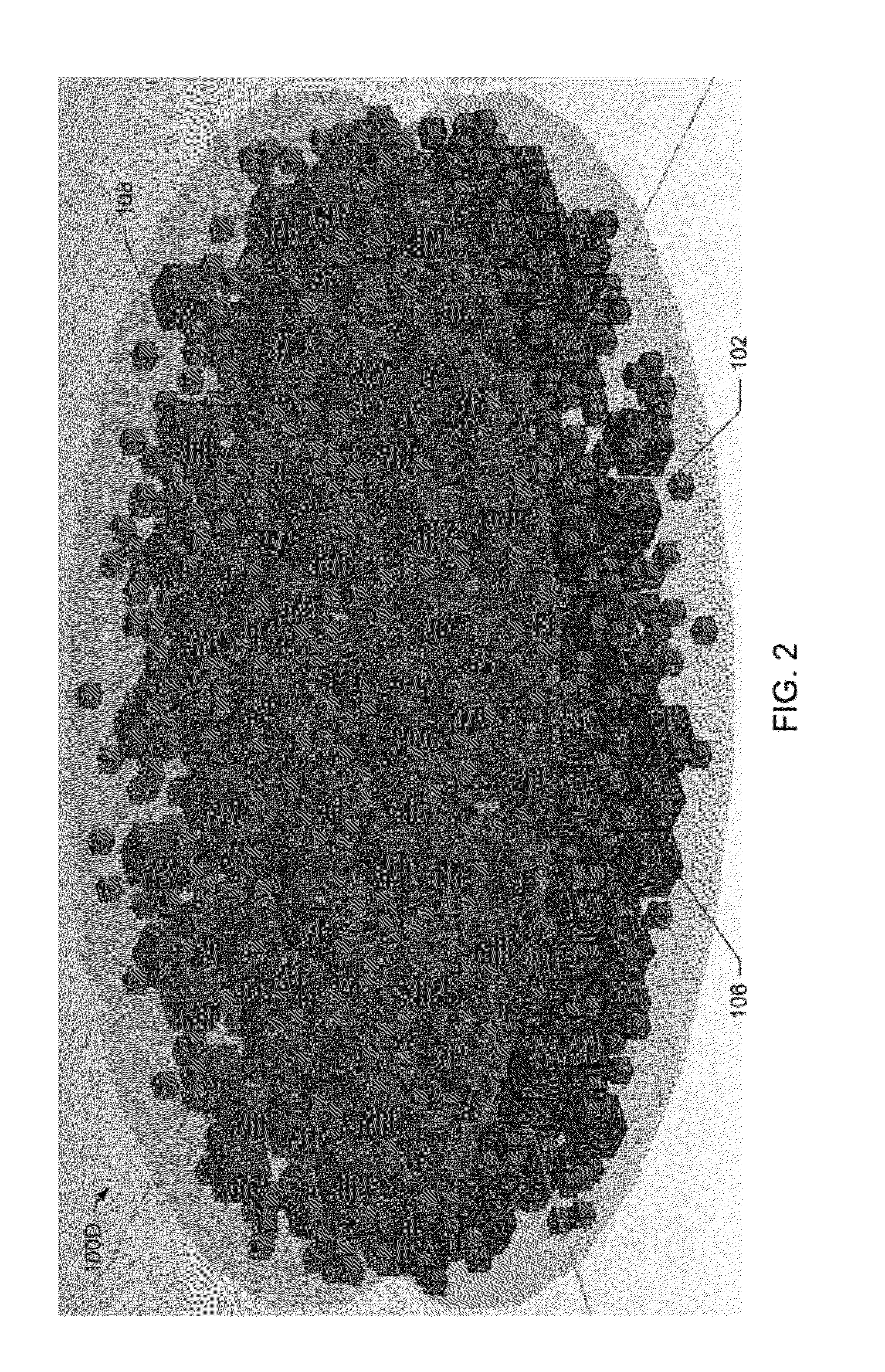
[0086]By way of example and not limitation, another exemplary method is provided for producing a composite material with a dielectric constant between 400 and 600 at frequencies between 200 MHz and 4.5 GHz. Initially, a mixture of perovskite ceramic particles was prepared. The mixture was composed of 72 wt % BaTiO3 particles with diameters between 65 μm and 150 μm, 21 wt % BaTiO3 particles with diameters between 0.5 μm and 3 μm, and 7 wt % BaTiO3 and BST particles with diameters less than 100 nm. The ceramic powder was mixed with a mixer mill for approximately two minutes. Caution was exercised to avoid excessive mixing that could have resulted in milling the larger particles down to smaller sizes.

[0087]Agar, primarily as agarose, was used as the polymer binder. While, stirring, the agar was heated and melted at a high concentration in water. While heated, the agar and water solution was slowly added to and mixed with the ceramic particles in a pre-heated container. The mixture was ...


PUM

PropertyMeasurementUnit
Lengthaaaaaaaaaa
Lengthaaaaaaaaaa
Lengthaaaaaaaaaa

Abstract

The present invention relates to composite materials with a high dielectric constant and high dielectric strength and to methods of producing the composite materials. The composite materials have high dielectric constants at a range of high frequencies and possess robust mechanical properties and strengths, such that they may be machined to a variety of configurations. The composite materials also have high dielectric strengths for operation in high power and high energy density systems. In one embodiment, the composite material is composed of a trimodal distribution of ceramic particles, including barium titanate, barium strontium titanate (BST), or combinations thereof and a polymer binder.

Description

CROSS REFERENCE TO RELATED APPLICATIONS[0001]This application claims priority to U.S. Provisional Application No. 61 / 466,604, filed on Mar. 23, 2011, and entitled “High Dielectric Constant Composite Material,” which is incorporated herein by reference in its entirety.FEDERALLY SPONSORED RESEARCH OR DEVELOPMENT[0002]This invention was made with government support under Grant No. N000-14-08-1-0267 from the Office of Naval Research. The Government has certain rights to this invention.FIELD OF THE INVENTION[0003]The invention relates generally to the field of composite materials, and, more particularly, to a composite material with a high dielectric constant. The composite materials may be used in a variety of applications requiring high-dielectric materials, including antennas, capacitors, and high voltage insulators, among others. The invention further relates to methods of manufacturing high dielectric constant composite materials and devices incorporating the composite material.BACK...

Claims


Application Information

Patent Timeline
IPC IPC(8): C04B35/468B29C43/52C04B35/00C04B35/462C04B35/47H01B19/00H01G4/20H01G4/008H01Q1/36H01Q1/38B29C69/00C04B35/491B82Y30/00
CPCC04B35/4682Y10T29/49227C04B2235/483C04B2235/5427C04B2235/5436C04B2235/5445C04B2235/5454C04B2235/5472H01G4/206H01Q1/362B29C43/003H01B3/12C08K3/30C08L101/00C08K2003/2237C08K2003/2206C08K3/22C08K3/0033B29K2509/02H01B19/00B29C2035/0827B29C39/003B05D1/40B05D1/005B29K2101/00B82Y30/00C04B35/6316C08K3/24C08K3/013C04B35/01C04B35/468H01G4/12
Inventor CURRY, RANDY D.O'CONNOR, KEVIN
Owner UNIVERSITY OF MISSOURI
Why Eureka
Try Eureka