Reflective optical element and method for operating an EUV lithography apparatus

a technology of reflective optical elements and lithography equipment, which is applied in the direction of photomechanical equipment, lighting and heating equipment, instruments, etc., can solve the problems of reducing the reflectivity of the optically active surface, affecting the performance of the lithography equipment, and affecting the lithography performance of the euv lithography equipment, etc., to achieve the effect of high reflectivity values, sufficient long-term stability, and sufficient protection of the reflective optical elemen

Inactive Publication Date: 2012-10-04
CARL ZEISS SMT GMBH
View PDF3 Cites 25 Cited by
  • Summary
  • Abstract
  • Description
  • Claims
  • Application Information

AI Technical Summary

Benefits of technology

[0011]It has been found that the metallic contaminants, which can originate from hydrogen cleaning units, for example are, inter alia, zinc, tin, indium, tellurium, antimony, bismuth, lead, arsenic, selenium, germanium, silver, cadmium, mercury, sulfur, gold, copper, tungsten or the alloys thereof. Furthermore, it has been found that the influence of the contamination on the reflectivity by these metals is smaller if the reflective optical element exposed to said contamination has a topmost layer composed of a fluoride. This is because, firstly, such a layer acts as protection of the underlying reflective surface of the optical element against other types of contamination, such as oxidative contamination or carbon contamination, for instance. Secondly, the topmost layer composed of a fluoride has the effect that metallic contaminations adhere to a lesser extent on the topmost layer during operation. This has the advantage that the metallic contaminations can be removed more simply from the surface with cleaning gases, for example. Furthermore, it has been found that this applies equally to contamination layers composed of silicon dioxide, which can also be removed relatively simply with cleaning gases on account of the low adhesion on fluoride layers.
[0018]In a further embodiment, the metal fluoride is selected from a group comprising: magnesium fluoride (MgF2), aluminum fluoride (AlF3), cryolite (Na3AlF6) and chiolite (Na5Al3F14). With regard to these metal fluorides, sufficient experience concerning the coating behavior is available, thus resulting in sufficient process reliability for the production of corresponding reflective optical elements. For example, it is known that magnesium fluoride and lanthanum fluorides preferably grow in polycrystalline fashion, whereas aluminum fluoride and chiolite grow rather in amorphous fashion. Consequently, depending on the use or mixture of the metal fluorides, using the coating process parameters, it is possible to establish specific surface properties, such as the microroughness, for example. These fluorides are also harmless from a toxicological stand point so that these fluorides can be handled easily within a coating process.

Problems solved by technology

A further source of contamination is polymers, in particular hydrocarbons, which can originate for example from the materials used in the vacuum environment or from the vacuum pumps used in EUV lithography apparatuses, or from residues of photoresists which are used on the semiconductor substrates to be patterned, and which lead, under the influence of the operating radiation, to carbon contaminations on the reflective optical elements.
It has been found, however, that the cleaning units can also lead to contaminations in particular by metals which originate predominantly from the cleaning units themselves or, in chemical reaction with the atomic hydrogen, are extracted from materials or components within EUV lithography apparatuses, in particular as volatile metal hydrides.
Furthermore, it has been found that contaminations in the form of silicon compounds in interaction with EUV radiation lead to contamination layers composed of silicon dioxide (SiO2) on the optically active surfaces of the reflective optical elements, which, on account of their good adhesion on a topmost layer of the optically active surface composed of ruthenium, for example, cannot be cleaned using atomic hydrogen or other cleaning methods and lead to an appreciable reduction of the reflectivity of the optically active surfaces.
Secondly, the topmost layer composed of a fluoride has the effect that metallic contaminations adhere to a lesser extent on the topmost layer during operation.
In particular, contamination layers composed of silicon dioxide can be removed from a reflective surface having a topmost layer composed of a fluoride by the cleaning gases, which contamination layers cannot be removed for example from a reflective surface having a topmost layer composed of ruthenium by the cleaning gases.
Different reflectivity values over the reflective surface lead to imaging aberrations of the lithography apparatus.

Method used


Image

  • Reflective optical element and method for operating an EUV lithography apparatus
  • Reflective optical element and method for operating an EUV lithography apparatus
  • Reflective optical element and method for operating an EUV lithography apparatus

Examples


Embodiment Construction

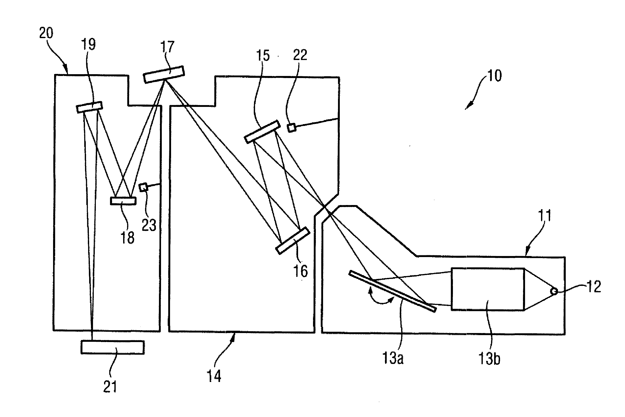
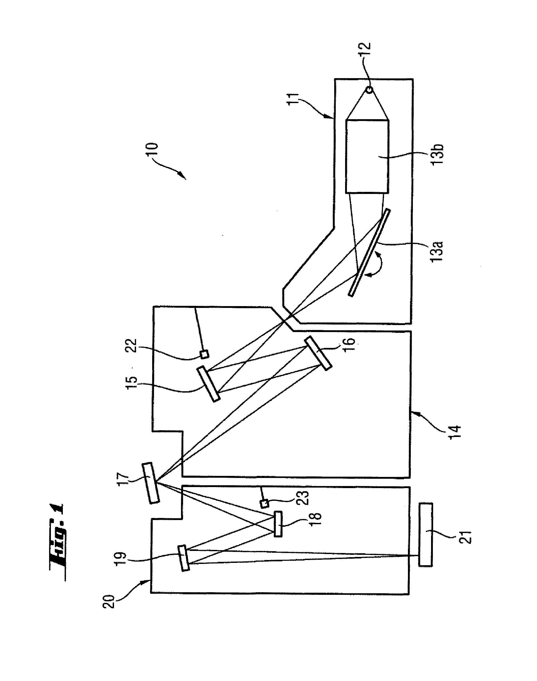
[0034]FIG. 1 schematically illustrates an EUV lithography apparatus 10. Essential components are the beam shaping system 11, the illumination system 14, the photomask 17 and the projection system 20. The EUV lithography apparatus 10 is operated under vacuum conditions in order that the EUV radiation is absorbed as little as possible in its interior.

[0035]The beam shaping system 11 comprises a radiation source 12, a collimator 13b and a monochromator 13a. By way of example, a plasma source or else a synchrotron can serve as radiation source 12. The emerging radiation in the wavelength range of approximately 5 nm to 20 nm is firstly concentrated in the collimator 13b. In addition, the desired operating wavelength is filtered out with the aid of a monochromator 13a. In the wavelength range mentioned, the collimator 13b and the monochromator 13a are usually embodied as reflective optical elements. In the case of the collimators, a distinction is made between so-called normal-incidence a...


PUM


Abstract

In order to reduce the adverse influence of contamination composed of silicon dioxide, hydrocarbons and / or metals within an EUV lithography apparatus on the reflectivity, a reflective optical element (50) for the extreme ultraviolet wavelength range having a reflective surface (59) is proposed, wherein the multilayer coating of the reflective surface (59) has a topmost layer (56) composed of a fluoride. The contaminations mentioned, which deposit on the reflective optical element (50) during the operation of the EUV lithography apparatus, are converted into volatile compounds by the addition of at least one of the substances mentioned hereinafter: atomic hydrogen, molecular hydrogen, perfluorinated alkanes such as e.g. tetrafluoromethane, oxygen, nitrogen and / or helium.

Description

[0001]This application is a Continuation of International Application No. PCT / EP2010 / 063694, filed on Sep. 17, 2010, which claims the benefit of U.S. Provisional Application No. 61 / 247,269, filed Sep. 30, 2009, and also claims the priority of German Application No. 2009 045 170.6, also filed on Sep. 30, 2009. The entire disclosures of all three of these applications are hereby incorporated into the present Continuation Application by reference.FIELD AND BACKGROUND [0002]The present invention relates to a reflective optical element for the extreme ultraviolet (EUV) wavelength range having a reflective surface. Moreover, the present invention relates to a method for operating an EUV lithography apparatus comprising a reflective optical element having a reflective surface. Furthermore, the present invention relates to an EUV lithography apparatus comprising a reflective optical element, to an illumination system, in particular for an EUV lithography apparatus, comprising a reflective o...

Claims


Application Information

Patent Timeline
Patent Type & Authority Applications(United States)
IPC IPC(8): G02B5/08
CPCB82Y10/00B82Y40/00G02B5/0825G02B5/0891G03F1/24G03F7/70316G21K2201/067G03F7/70925G03F7/70941G03F7/70958G03F7/70983G21K1/062G21K2201/061G03F7/70916G03F7/20G21K1/06G02B5/08
Inventor EHM, DIRK HEINRICHDOCHNAHL, AXELVON BLANCKENHAGEN, GISELA
Owner CARL ZEISS SMT GMBH
Why Eureka
Try Eureka