Bubbling bed catalytic hydropyrolysis process utilizing larger catalyst particles and smaller biomass particles featuring an Anti-slugging reactor

a catalytic hydropyrolysis and biomass particle technology, which is applied in the direction of physical/chemical process catalysts, metal/metal-oxide/metal-hydroxide catalysts, hydrocarbon oil treatment products, etc., can solve the problems of inability to realize practical or economic viability, inability to transport and utilize this product, and chemically unstable liquid produced by conventional pyrolysis tend to thicken, etc. , to achieve the effect of inhibiting the slugging of the bed

Active Publication Date: 2012-10-18
GAS TECH INST
View PDF1 Cites 29 Cited by
  • Summary
  • Abstract
  • Description
  • Claims
  • Application Information

AI Technical Summary

Benefits of technology

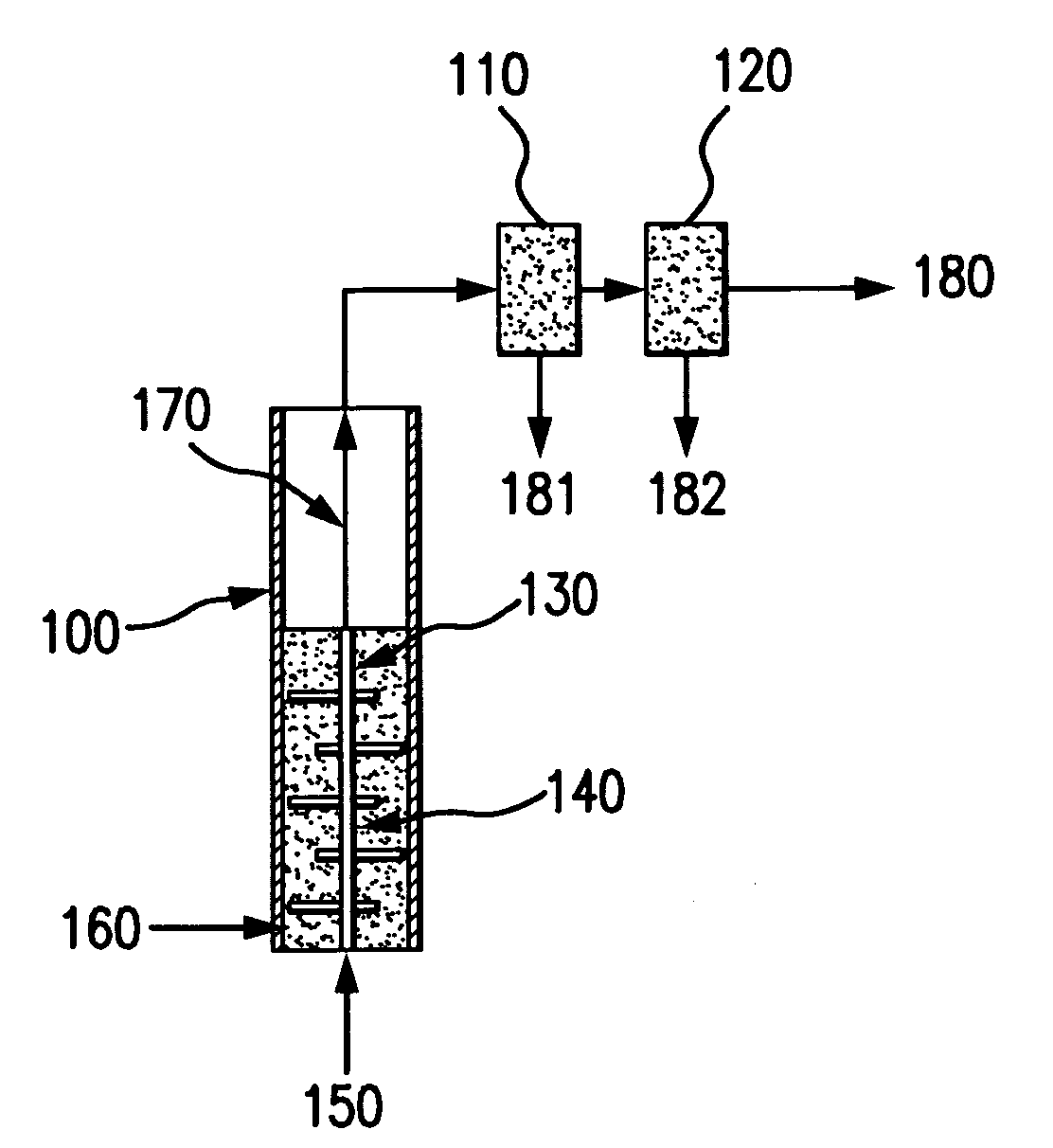
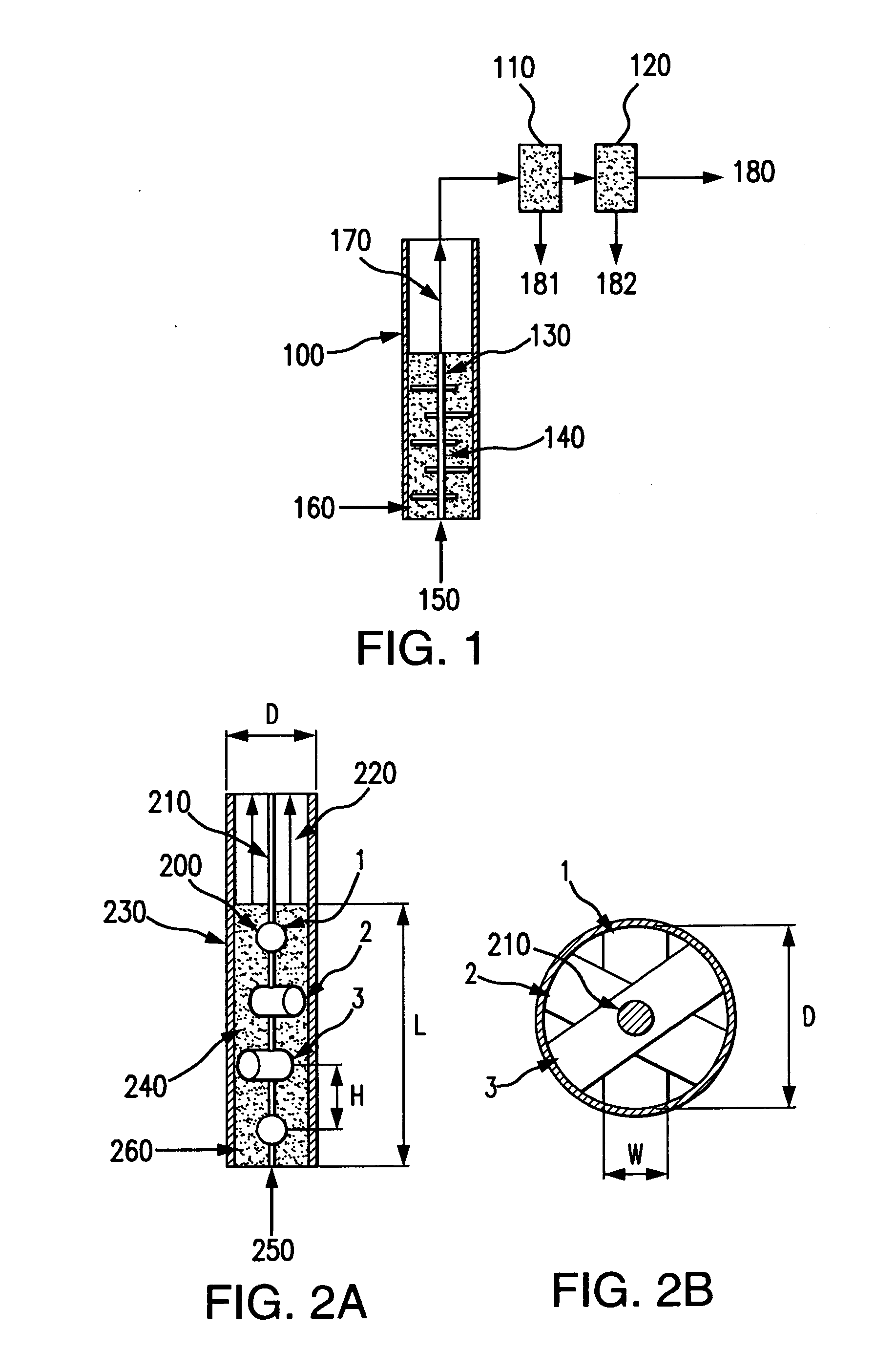
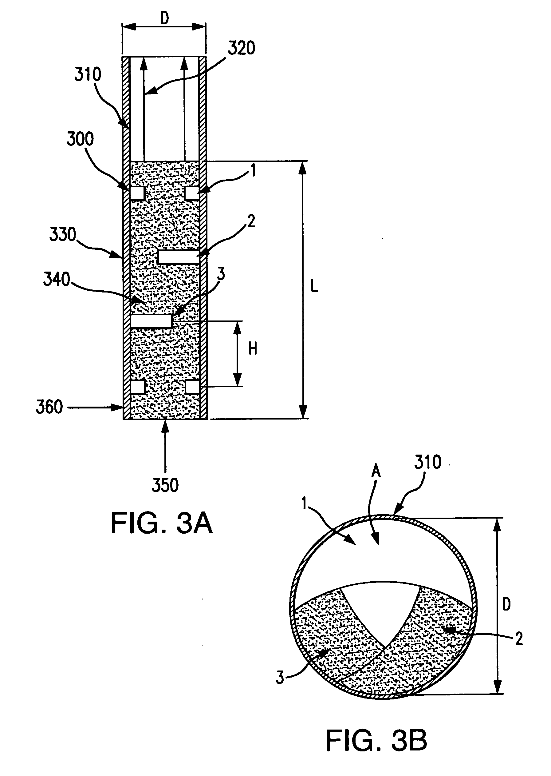
[0015]This invention relates to a process for thermochemically transforming biomass or other oxygenated feedstocks into high quality liquid hydrocarbon fuels. In particular, a catalytic hydropyrolysis reactor, containing a deep bed (length:diameter ratio >1.5) of fluidized catalyst particles is utilized. The reactor accepts particles of biomass or other oxygenated feedstocks that are significantly smaller than the particles of catalyst in the fluidized bed. The reactor preferably features an insert or other structure disposed within the reactor vessel that inhibits slugging of the bed and thereby minimizes attrition of the catalyst. Within the bed, the biomass feedstock is converted into a vapor-phase product, containing hydrocarbon molecules and other process vapors, and an entrained solid char product, which is separated from the vapor stream after the vapor stream has been exhausted from the top of the reactor. When the product vapor stream is cooled to ambient temperatures, a significant proportion of the hydrocarbons in the product vapor stream can be recovered as a liquid stream of hydrophobic hydrocarbons, containing less than 4% by mass of oxygen, with properties consistent with those of gasoline, kerosene, and diesel fuel. Separate streams of gasoline, kerosene, and diesel fuel may also be obtained, either via selective condensation of each type of fuel, or via later distillation of the combined hydrocarbon liquid.

Problems solved by technology

The chemically unstable liquids produced by conventional pyrolysis tend to thicken over time and can also react to a point where hydrophilic and hydrophobic phases form.
Dilution of pyrolysis liquids with methanol or other alcohols has been shown to reduce the subsequent activity and viscosity of the oils, but this approach is not considered to be practically or economically viable, because large amounts of unrecoverable alcohol would be required to stabilize large amounts of pyrolysis liquids for transport and subsequent use.
As a result, transport and utilization of this product are problematic and it is difficult to upgrade this product to a liquid fuel due to retrograde reactions that typically occur in conventional pyrolysis and in conventional fast pyrolysis.
In addition, the separation of char generated during conventional pyrolysis from the liquid pyrolysis product presents a technical challenge due to the large amounts of oxygen, olefins, acids, and free radicals in hot pyrolysis vapors which remain highly reactive and form a pitch-like material when they come in intimate contact with char particles on the surface of a barrier filter, inertial separation device, or electrostatic precipitator.
In particular, barrier filters used to separate the char from the hot pyrolysis vapors (prior to cooling and condensation of the liquid pyrolysis products) can quickly experience irreversible clogging (blinding) due to the reactions of char and reactive vapors that occur on and within the layer of char on the surface of the filter.
However, the upgrading of conventional pyrolysis liquids via hydroconversion is commercially non-viable.
This approach consumes large amounts of hydrogen, thus making the process economically unattractive.
In addition, hydroconversion reactors often plug due to accumulations of coke precursors present in the pyrolysis oils or from coke products resulting from catalysis.
The coke is a solid product, consisting mostly of carbon, and the maintenance needed to remove it from hydroconversion reactors reduces further the economic viability of hydroconversion of conventional pyrolysis liquids.
Hydropyrolysis can be carried out with or without the aid of a catalyst However, lower hydrocarbon yields and lower deoxygenation tend to be a characteristic of noncatalytic hydropyrolytic processes.
Unfortunately, this approach compromises economy, as it requires an external source of H2 and must be carried out at high reactor pressures.
In addition to requiring a continuous external input of hydrogen, such conventional hydropyrolysis processes produce excessive H2O which generally represents a waste stream.
In this type of reactor, the hydropyrolysis of biomass has not been found to be economically attractive because the oxygen content of the hydrocarbon product was still fairly high after processing and the reaction conditions required by the process were too severe to be practical.
Fluidized beds may be adversely affected by a phenomenon referred to as “slugging.” Slugging develops in beds that have L / D ratios greater than 1.5-2.0 and fluidized beds composed of particles larger than a few hundred microns are especially prone to slugging.
Slugging is undesirable for several reasons.
The uniformity of axial temperature is thereby compromised, and considerable gradients in temperature can be observed along the height of the bed.
Slugging also creates cyclical stresses on the walls and floor of the bed, particularly if the bed is disposed within a reactor, and the effect of cyclic loading and unloading on the reactor support structure, and the concomitant effect on process chemistry, can destroy any semblance of process uniformity.
The vibration, or cyclical loading, of the reactor walls and support structure, can lead to mechanical failures, and the variation in the process chemistry will also make it impossible to operate with a useful level of process control.
However, there are applications where a shallow bed is simply not practical.
However, the flow rate is not large enough to entrain the solid catalyst particles from which the bed is composed in the gaseous exhaust stream and permanently separate them from the bed.

Method used


Image

  • Bubbling bed catalytic hydropyrolysis process utilizing larger catalyst particles and smaller biomass particles featuring an Anti-slugging reactor
  • Bubbling bed catalytic hydropyrolysis process utilizing larger catalyst particles and smaller biomass particles featuring an Anti-slugging reactor
  • Bubbling bed catalytic hydropyrolysis process utilizing larger catalyst particles and smaller biomass particles featuring an Anti-slugging reactor

Examples


examples

[0120]Fluidized Bed Mixing Studies without Insert

[0121]Experiments were carried out in order to study slugging in bubbling fluidized beds, consisting of relatively large, spherical solid particles similar to the catalyst used in the hydropyrolysis process of the present invention. The bed material consisted of porous alumina spheres, with a mean diameter of 1800 microns. The diameters of the particles of bed material were all within plus or minus 200 microns of the mean diameter. The bulk density of the bed material was 0.75 kilograms per liter.

[0122]Fluidized beds expand as fluidizing gas is passed through them, so they are most readily compared on an unexpanded basis. In this case, the unexpanded depth of the bed is the depth of the bed when no fluidizing gas is passing through it.

[0123]Beds with an unexpanded L / D near 6 were studied in two clear plastic tubes. One tube had an inner diameter of 3.33 centimeters, and the other had an inner diameter of 7.62 centimeters. The smaller ...


PUM

PropertyMeasurementUnit
partial pressureaaaaaaaaaa
temperatureaaaaaaaaaa

Abstract

This invention relates to a process for thermochemically transforming biomass or other oxygenated feedstocks into high quality liquid hydrocarbon fuels. In particular, a catalytic hydropyrolysis reactor, containing a deep bed of fluidized catalyst particles is utilized to accept particles of biomass or other oxygenated feedstocks that are significantly smaller than the particles of catalyst in the fluidized bed. The reactor features an insert or other structure disposed within the reactor vessel that inhibits slugging of the bed and thereby minimizes attrition of the catalyst. Within the bed, the biomass feedstock is converted into a vapor-phase product, containing hydrocarbon molecules and other process vapors, and an entrained solid char product, which is separated from the vapor stream after the vapor stream has been exhausted from the top of the reactor. When the product vapor stream is cooled to ambient temperatures, a significant proportion of the hydrocarbons in the product vapor stream can be recovered as a liquid stream of hydrophobic hydrocarbons, with properties consistent with those of gasoline, kerosene, and diesel fuel. Separate streams of gasoline, kerosene, and diesel fuel may also be obtained, either via selective condensation of each type of fuel, or via later distillation of the combined hydrocarbon liquid.

Description

BACKGROUND OF THE INVENTION[0001]1. Field of the Invention[0002]This invention relates to a process for thermochemically transforming biomass or other oxygenated feedstocks into high quality liquid hydrocarbon fuels.[0003]2. Description of Related Art[0004]Oxygenated feedstocks, such as solid biomass (wood, agricultural waste, waste paper, etc.) can be converted into liquid products via rapid heating in the absence of oxygen (pyrolysis). A solid char product (consisting mostly of carbon, but also containing any non-volatile, inert compounds found in the feedstock) and non-condensable vapors (such as CO2 and CH4) are produced, along with condensable species such as: water, hydrocarbons, and molecules that contain carbon atoms, hydrogen atoms, and oxygen atoms. The proportions of the resulting products obtained depends on the rate of heating of the feedstock particles, as described by Mohan, et al. (Mohan, Pittman, and Steele, “Pyrolysis of Wood / Biomass for Bio-oil: A Critical Review,...

Claims


Application Information

Patent Timeline
Patent Type & Authority Applications(United States)
IPC IPC(8): C10L1/18
CPCB01J8/1809Y02E50/32B01J2208/0084C10G1/06C10G1/086C10G1/10C10G3/45C10G3/50C10G3/57C10G2300/1014C10G2300/1018C10G2300/202B01J23/755B01J23/882C10L1/04C10G3/46B01J2208/00061B01J2208/00115B01J2208/00548B01J2219/00252C10G2300/1003C10G2400/02C10G2400/04C10G2400/08Y02E50/14B01J8/34Y02P30/20C10G1/002Y02E50/30Y02E50/10B01J8/18C10G1/08C10G3/00C10L1/02C10L2200/0469C10L2290/02
Inventor MARKER, TERRY L.FELIX, LARRY G.LINCK, MARTIN B.ROBERTS, MICHAEL J.
Owner GAS TECH INST
Why Eureka
Try Eureka