Pattern data conversion for lithography system

a lithography system and pattern data technology, applied in image data processing, radiation therapy, nanotechnology, etc., can solve the problems of large amount of pattern data required to enable the scanning process, significant drawback, and inability to determine the actual memory requirement to store pattern data in advance, so as to improve performance, and reduce the effect of performan

Active Publication Date: 2012-11-15
MAPPER LITHOGRAPHY IP +1
View PDF14 Cites 28 Cited by
  • Summary
  • Abstract
  • Description
  • Claims
  • Application Information

AI Technical Summary

Benefits of technology

[0012]The re-sampling may optionally comprise transforming a pixel size of the intermediate pattern data, and the pixel size of the intermediate pattern may be larger or smaller than a pixel size of the output pattern data. Transforming the pixel size, so that the pixel size of the output pattern data is different from the pixel size of the intermediate pattern data, permits making adaptations which improve performance.
[0013]Although a double quantization reduces performance in comparison to a single quantization in terms of lithographic errors (e.g. critical dimension uniformity and overlay), the performance reduction may be decreased by using more data to store the pattern after the first quantization than the amount of data that remains after the second quantization. For example, intermediate pattern data which has a pixel size of 5 nm with 4-bit grey level pixel values after the first quantization (or pixel size of 2.5 nm with 1-bit B / W pixel values) contains more data than output patter data with a pixel size of 3.5 nm with 1-bit bi-level B / W pixel values. Ideally the intermediate pattern data has a very high resolution after the first quantization step, but this requirement is balanced against the cost and complexity of storing such a large amount of data. The change in pixel size during re-sampling enables this adjustment of data resolution from intermediate to output pattern data.
[0014]Changing the pixel size also enables changing the exposure dose without changing the transmission rate of the output pattern data to the column of the lithography machine which cannot be easily changed. By changing the scanning speed of the beamlets and the pixel size of the output pattern data the dose rate may be changed (the pixel size of the output pattern data can also become rectangular due to this).

Problems solved by technology

When exposing a target at very high resolution, a very large amount of pattern data is required to enable the scanning process.
However, a vector format has the disadvantage it is non-deterministic, so the amount of memory required to store the data is a function of the pattern data, and the actual memory requirement to store the pattern data cannot be determined in advance.
This is a significant drawback in view of the very large size of the pattern data.

Method used


Image

  • Pattern data conversion for lithography system
  • Pattern data conversion for lithography system
  • Pattern data conversion for lithography system

Examples


Embodiment Construction

[0046]The following is a description of various embodiments of the invention, given by way of example only and with reference to the drawings.

Charged Particle Lithography System

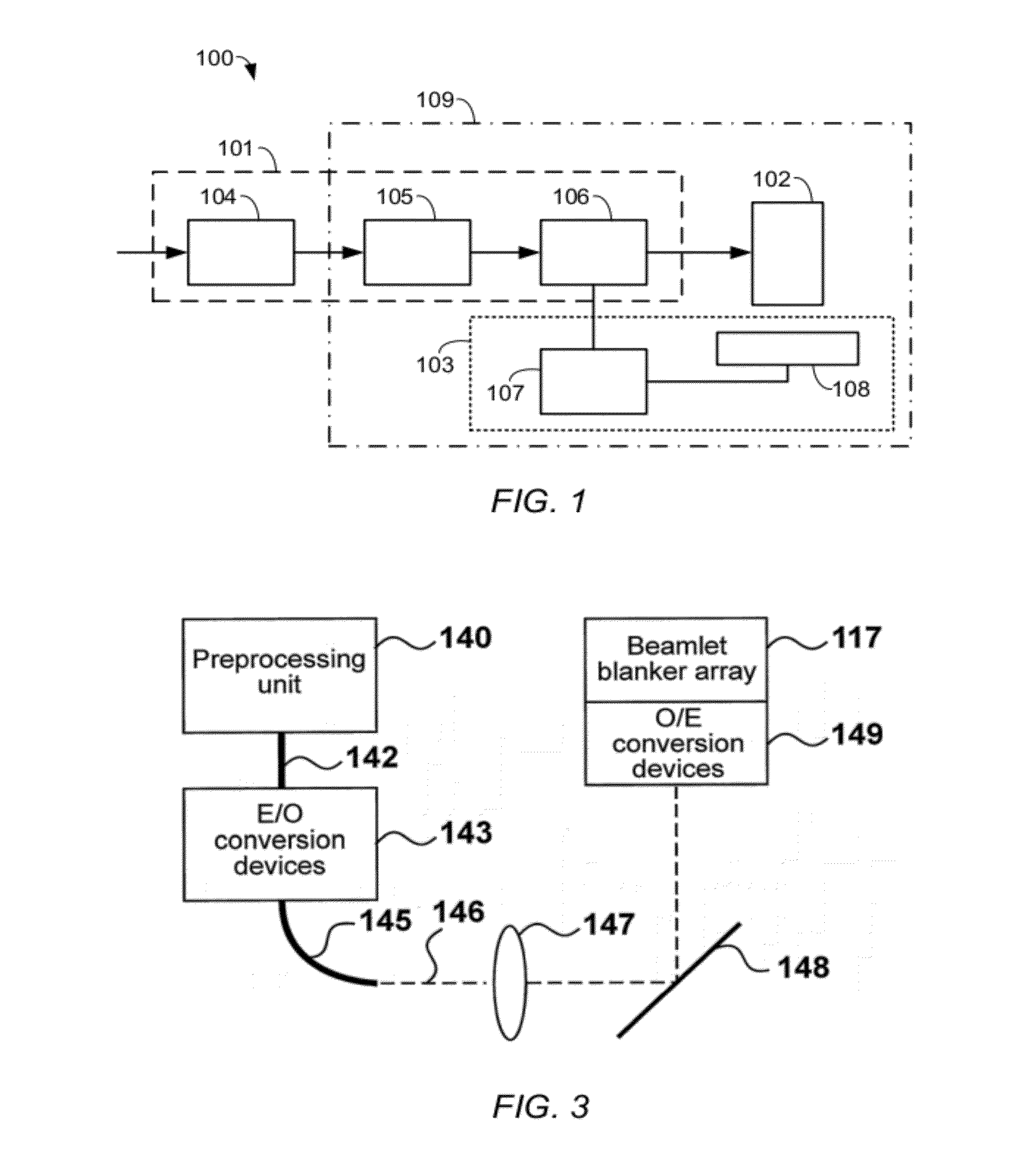
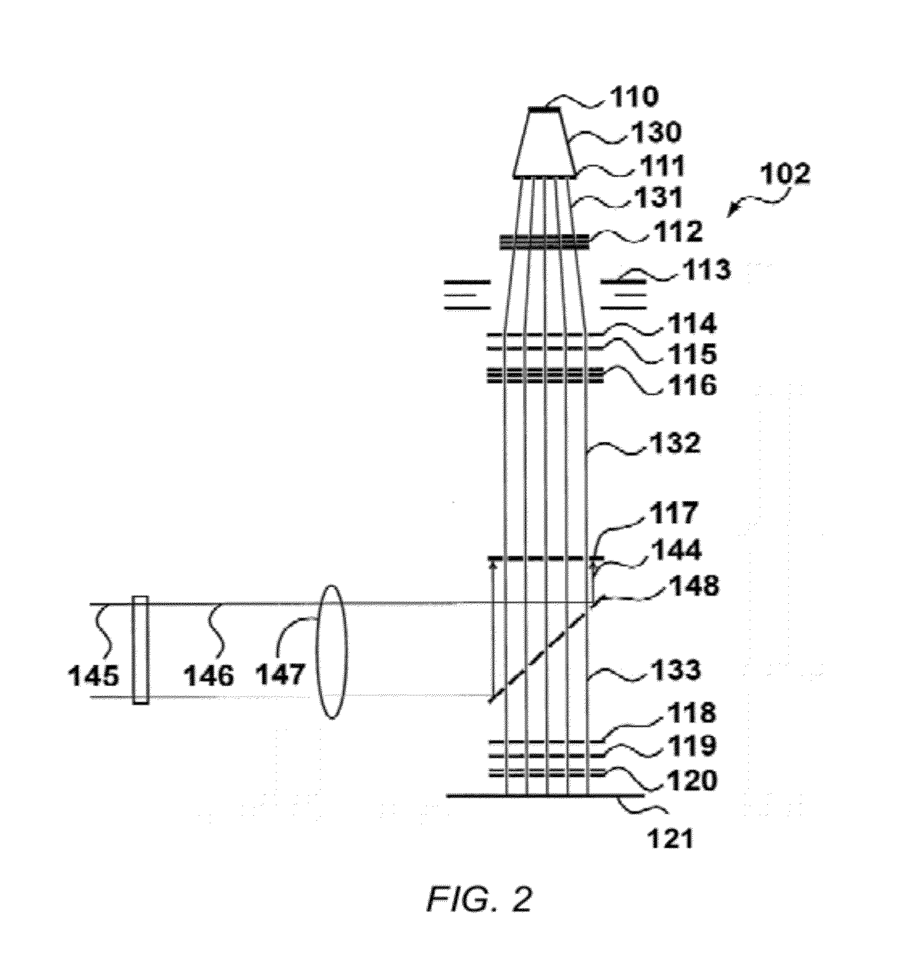
[0047]FIG. 1 is a conceptual diagram showing a maskless lithography system 100 divided into three high level sub-systems: a data path 101, a lithography machine column 102, and wafer positioning system 103. The lithography machine column 102 generates optical or charged particle beams for exposing a wafer according a pattern data provided by the data path. The wafer positioning system 103 moves the wafer under the column 102 to enable scanning of the wafer by the exposure beams generated by the column 102.

[0048]The wafer positioning system 103 typically includes a control system 107 controlling movement of a wafer table 108 on which the wafer is placed. In one embodiment, the wafer positioning system moves the wafer in an x-direction while the beams are scanned across the surface of the wafer in a y-direction...


PUM


Abstract

A method and system for exposing a target according to pattern data in a maskless lithography machine generating a plurality of exposure beamlets for exposing the target. The method comprises providing input pattern data in a vector format, rendering and quantizing the input pattern data to generate intermediate pattern data, and re-sampling and re-quantizing the intermediate pattern data to generate output pattern data. The output pattern data is supplied to the lithography machine, and the beamlets generated by the lithography machine are modulated on the basis of the output pattern data.

Description

CROSS REFERENCE TO RELATED APPLICATIONS[0001]This application is a continuation of PCT application number PCT / IB2010 / 052180 filed on 17 May 2010, which claims priority from U.S. provisional application No. 61 / 179,765 filed on 20 May 2009, U.S. Provisional application 61 / 179,760 filed on 20 May 2009 and U.S. provisional application 61 / 257,122 filed on 2 Nov. 2009. All applications are hereby incorporated by reference in their entireties.BACKGROUND OF THE INVENTION[0002]1. Field of the Invention[0003]The present invention relates to a maskless lithography apparatus, and in particular to a system and method for converting vector format pattern data for use by a lithography apparatus.[0004]2. Description of the Related Art[0005]A maskless lithography machine generates optical or particle beamlets for exposing a target. The machine requires pattern data for modulating the beamlets as they are scanned over the surface of the target. When exposing a target at very high resolution, a very l...

Claims


Application Information

Patent Timeline
Patent Type & Authority Applications(United States)
IPC IPC(8): G21K5/00G09G5/02G06T1/00
CPCB82Y10/00B82Y40/00H01J37/3174G03F7/70508G03F7/70291H01J37/304H01J37/317
Inventor VAN DE PEUT, TEUNISWIELAND, MARCO JAN-JACO
Owner MAPPER LITHOGRAPHY IP
Why Eureka
Try Eureka