
Method for purifying silicon

a technology of purification method and silicon, applied in the direction of crystal growth process, polycrystalline material growth, silicon compound, etc., can solve the problems of insufficient photoelectric conversion efficiency, high photoelectric conversion efficiency, and defects of solar cells, so as to reduce the contents, reduce the effect of harmful impurities and effectively remove harmful impurities

Inactive Publication Date: 2013-01-10
INTIRAYMI SILICON TECH
View PDF0 Cites 0 Cited by
  • Summary
  • Abstract
  • Description
  • Claims
  • Application Information

AI Technical Summary

Benefits of technology

The present invention provides a new method for purifying silicon to remove harmful impurities simultaneously, specifically boron and phosphor. This method increases the purity of silicon to 4N or 5N, which is required for solar cells. The purification process allows for the removal of all impurities simultaneously, resulting in higher purity silicon. This method helps to meet the requirements for high-purity silicon needed for solar cells.

Problems solved by technology

The actual result shows that the prepared solar cells have the defects: the photoelectric conversion efficiency is insufficiently high and deteriorates rapidly.
This shows that the content of impurities in the high purity silicon prepared by the prior art methods is still unstable and the purity of silicon needs to be further improved.
Therefore, the metallurgy method in prior art is still unable to meet the requirement of solar cells.
The continuation of the reaction depends on the concentration diffusion of boron atoms and phosphorus atoms which have low (ppm) concentration inside silicon and the effect of a single operation is limited.
The process of high-temperature evaporation also results in the pollution of silicon by environment.
The segregation coefficient of boron and phosphor is so big that the purification result of a single directional solidification is not good.
Besides, among the methods of prior art for removing boron and phosphor, there is not one method with which two said impurities can be removed at the same time.

Method used


Image

  • Method for purifying silicon
  • Method for purifying silicon
  • Method for purifying silicon

Examples


example 1

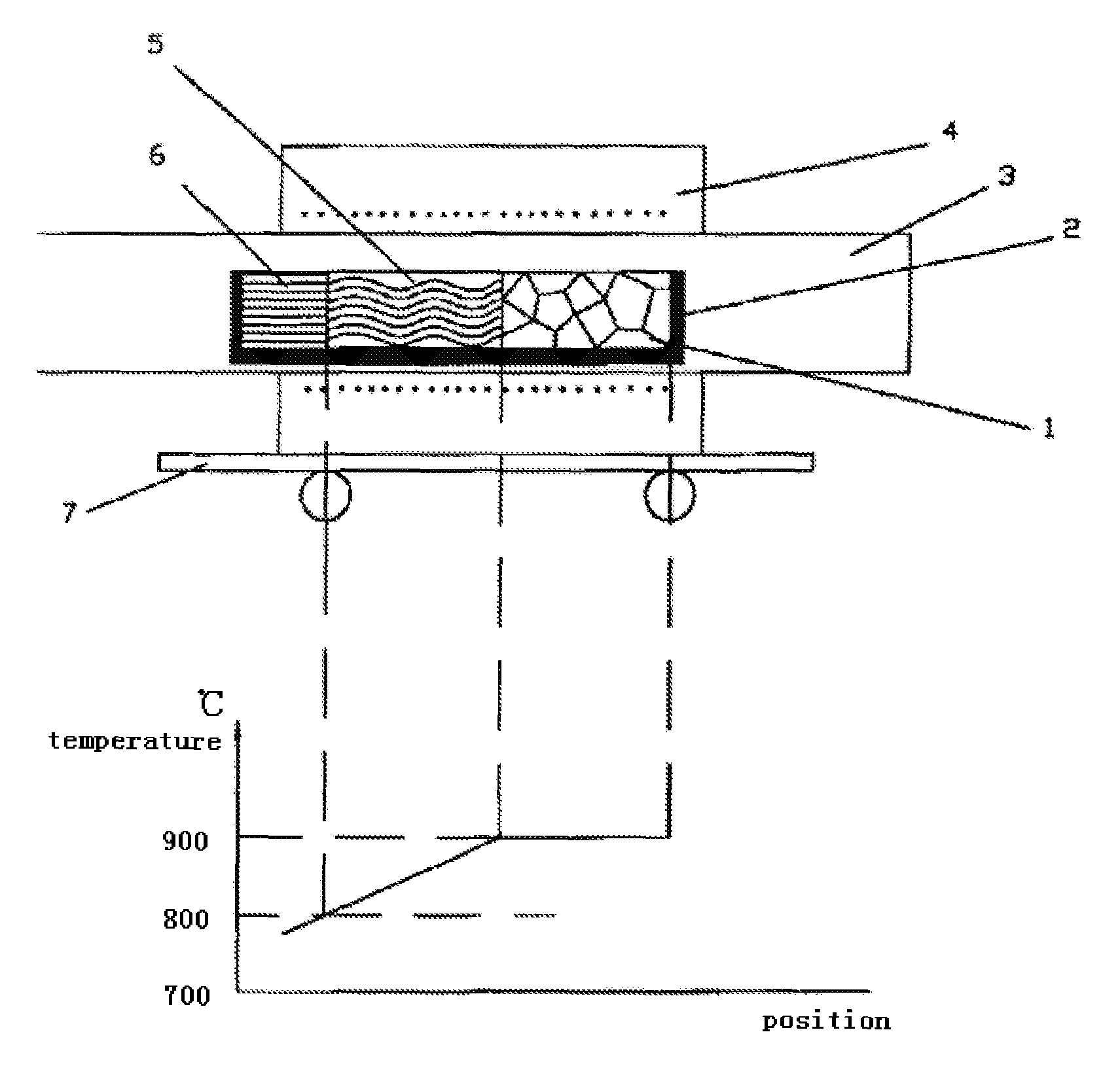
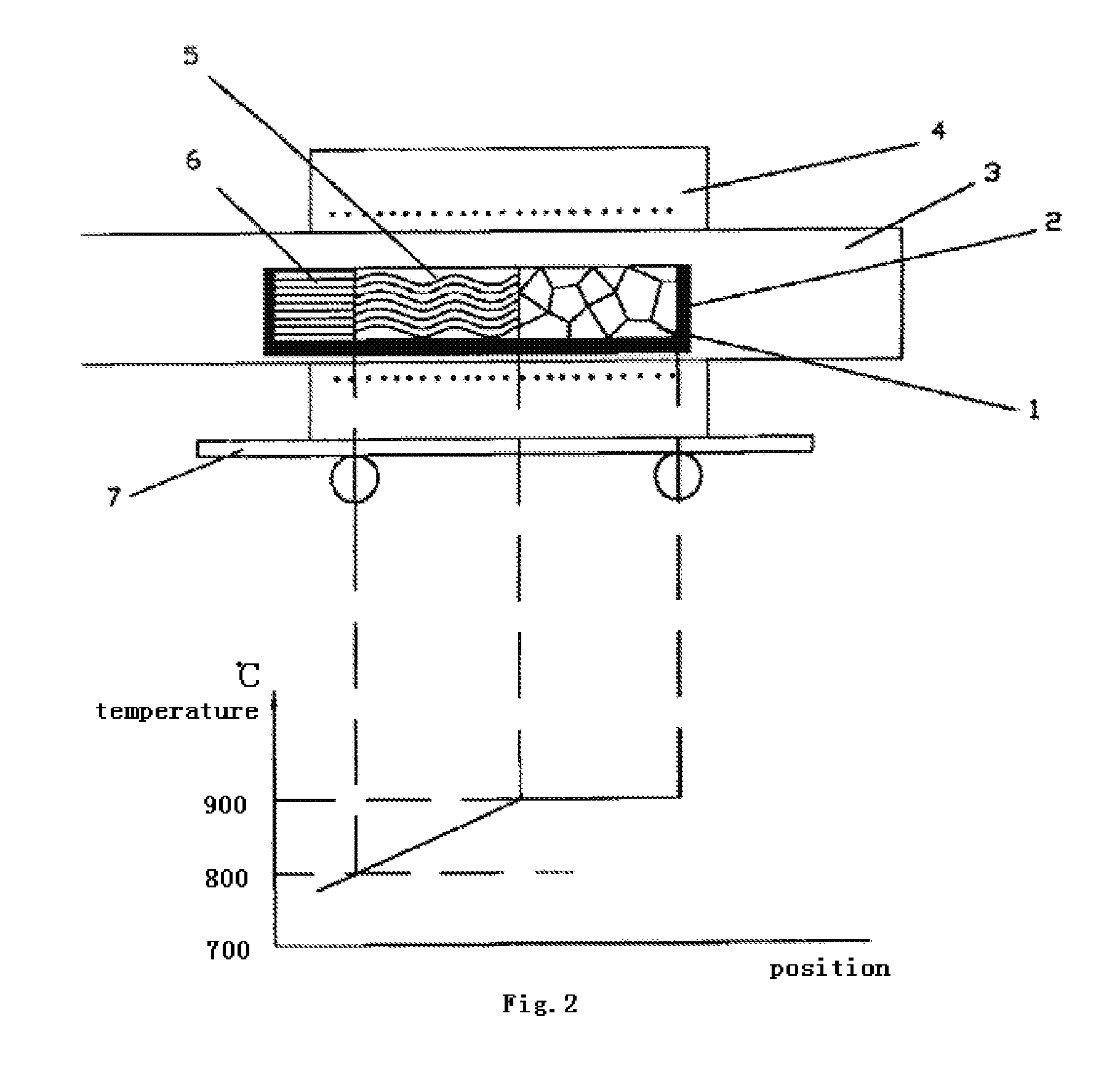
[0043]The spread process of the silicon solute and the temperature distribution of the heating furnace are illustrated in the schematic diagram of FIG. 2. The steps for purifying silicon are as follows:

[0044](1) Mix aluminum with the purity 4N or 5N with silicon with the purity 4N or 5N in proportion as silicon accounts for 26% of total aluminum by weight and melting the aluminum-silicon mixture in the graphite boat 2 under air pressure of 10−2 Pa. The quartz tube 3 is taken out of the heating furnace 4 immediately after the components are uniformly mixed. The square shaped aluminum-silicon alloy ingot is obtained upon the cooling down of the materials. The aluminum-silicon alloy ingot is taken out after being cooled down to room temperature. The surface thereof is polished, rinsed and dried for later use. Besides, the high-purity silicon with the purity 4N or 5N is also prepared for later use by cleaning and drying its surface.

[0045](2) Weigh silicon with the purity 4N or 5N in the...

example 2

[0050](1) Prepare aluminum with the purity 4N or 5N and silicon with the purity 4N or 5N according to a ratio by weight of aluminum:silicon=74% :146% and place both of them in the graphite boat 2 at the same time, wherein aluminum is on the left side and silicon is on the right side.

[0051](2) Close the quartz tube 3 and starting the vacuum system. Start to heat when air pressure is lower than 10−2 Pa. The heating furnace 4 controls the graphite boat 2 to be completely within 800° C. range and maintains the temperature constant. When the dissolving concentration of silicon in aluminum becomes even, adjust the heating furnace to make the left side of the graphite boat maintain 800° C. and increase the temperature of right side in the meantime. When the temperature of the solid-liquid interface between the undissolved silicon on the right side and the aluminum-silicon melt reaches 900° C., the solute silicon starts to spread from right to left till the left side of the graphite boat an...

example 3

[0053]Conduct according to the device illustrated in FIG. 2. The steps included are as follows:

[0054](1) Prepare aluminum with the purity 4N or 5N and silicon with the purity 4N or 5N for the aluminum-silicon alloy containing ≧38% by weight of silicon and place them in the high-purity graphite boat 2. Heat them to melt under the atmosphere of the air pressure being lower than 10−2 Pa. Remove the quartz tube 3 out of the heating furnace 4 when the ingredients become even. The aluminum-silicon alloy ingot containing ≧38% of silicon with a square-shaped section is obtained after the materials cool down. Dry for later use after the surface thereof is polished and cleaned.

[0055](2) The silicon seed crystals with a square-shaped section which match the inner wall of the graphite boat are placed at the position 6 on the left side of the high-purity graphite boat 2 where pure silicon is segregated, the aluminum-silicon alloy ingot prepared in the above mentioned steps is placed at the posit...


PUM


Abstract

A method for purifying silicon includes placing silicon to be purified and an aluminum-silicon alloy ingot, made from high purity aluminum in close contact in a closed environment to be subjected to heating under vacuum, such that the aluminum-silicon alloy ingot is melted into an aluminum-silicon melt. The temperatures are kept constant when the temperature M the interface of the silicon and the aluminum-silicon melt and the temperature at a free end of the aluminum-silicon melt reach 900° C. and 800° C. respectively. As the purified silicon begins to segregate and the interface, the heating apparatus is moved in step with the growth rate of the segregated silicon toward the silicon to be purified to maintain the temperatures at both ends of the aluminum-silicon melt. The segregated pure silicon is cut off upon the completion of dissolution of purified silicon and after cooling and air pressure recovery.

Description

TECHNICAL FIELD [0001]The present invention relates to a method for manufacturing high-purity silicon. The manufactured silicon is used for solar cells.BACKGROUND ART [0002]Photovoltaic power generation is a technology converting light power directly into electrical power by using the photovoltaic effect of semiconductor interfaces. The key components of this technology are solar cells, and one of the key factors manufacturing solar cells is the preparation of high purity silicon.[0003]In order to lower the cost of the photovoltaic power generation and promote the transformation of the photovoltaic power generation into a principal energy, it is a strategic measure to avoid the modified Siemens process in the prior art which is high-cost, high-energy-consumption and environmental burden, and to seek new purification methods for manufacturing high purity silicon used in solar cells which are low-cost, low-energy-consumption and environment-friendly.[0004]Generally, the metallurgy met...

Claims


Application Information

Patent Timeline
IPC IPC(8): C30B9/10
CPCC01B33/037
Inventor JIANG, XUEZHAO
Owner INTIRAYMI SILICON TECH
Learn More