Plasma-Polymerized Polymer Coating

a polymer coating and polymer technology, applied in the direction of plasma technique, electrical apparatus construction details, association of printed circuit non-printed electric components, etc., can solve the problems of unsatisfactory parylene deposition technique, time-consuming and expensive deposition process, and high cost of starting materials, so as to improve the performance of conformal coating and improve the protection of electrical assemblies during operation.

Active Publication Date: 2013-02-07
HZO INC
View PDF8 Cites 35 Cited by
  • Summary
  • Abstract
  • Description
  • Claims
  • Application Information

AI Technical Summary

Benefits of technology

[0017]Technical advantages of particular embodiments may include improved performance of the conformal coating, which may result in improved protection of the electrical assembly during operation.

Problems solved by technology

However, the deposition process is time consuming and expensive, and the starting material is expensive.
The parylene deposition technique described above is not ideal because of the high cost of the starting material, the high thermal energy consumption during monomer generation, the high vacuum requirements and the low growth rate.
In addition, there are a number of other disadvantages that may be associated with the current conformal coatings.
Coated contacts would not be able to make an electrical connection to other devices, since the conformal coating can be thick and insulating.
Furthermore, it may be very difficult and expensive to remove the current conformal coatings if reworking of the electrical assembly is required.
There is no possibility of soldering or welding through the coatings, without prior removal.
Additionally, due to the liquid techniques that are generally used to deposit these conformal coatings, there is a tendency for defects, such as bubbles, to form in the coating.
These defects reduce the protective capabilities of the conformal coating.
A further problem with prior art conformal coatings is that, due to the liquid techniques used during coating, it may be difficult to deposit the coating underneath components on the assembly.

Method used


Image

  • Plasma-Polymerized Polymer Coating
  • Plasma-Polymerized Polymer Coating
  • Plasma-Polymerized Polymer Coating

Examples


example 1

XPS Analysis of a Plasma-Polymerized Fluorohydrocarbon

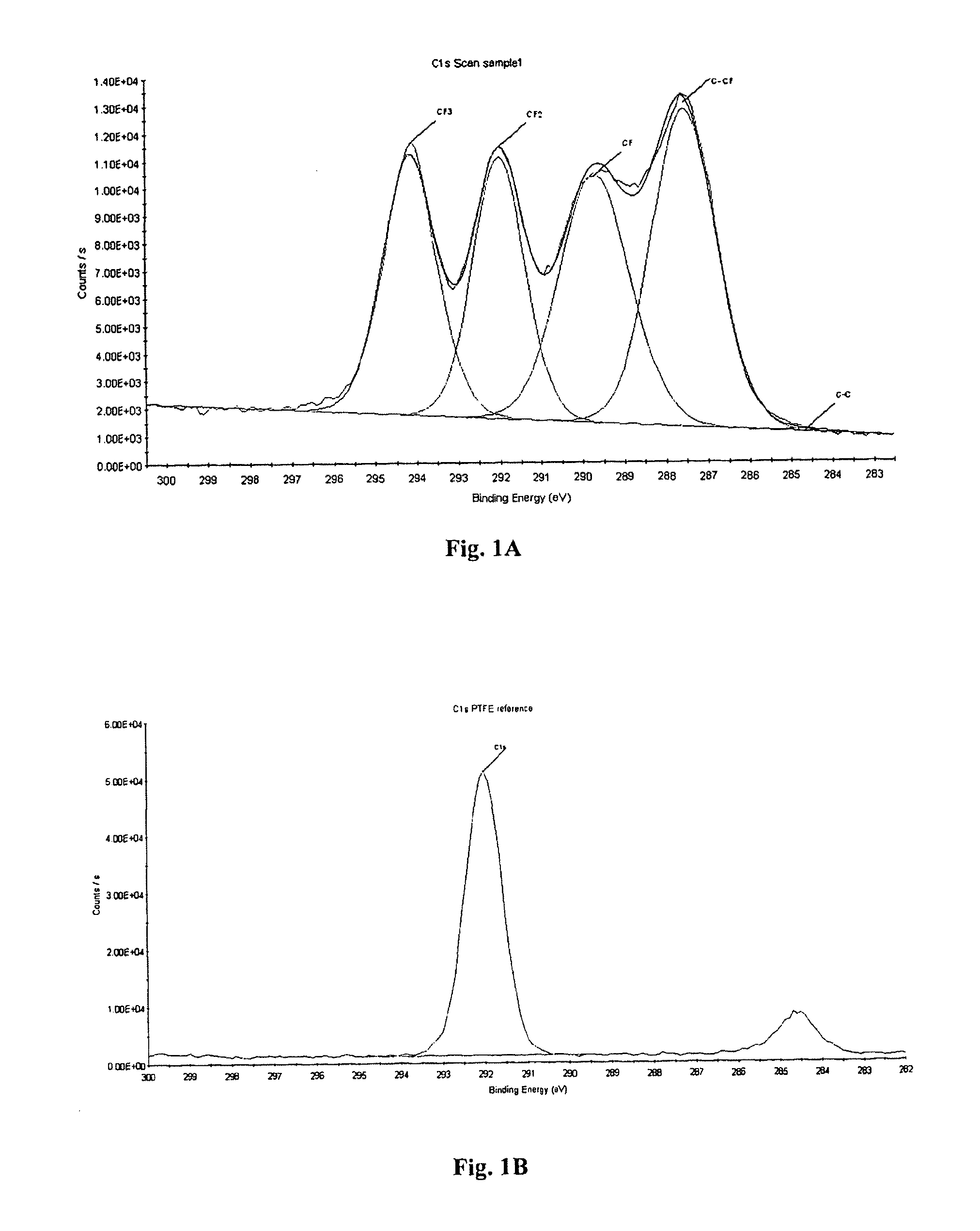
[0151]An epoxy laminate substrate was coated with a plasma-polymerized fluorohydrocarbon. This laminate was cut to yield a sample size of approximately 1 cm square and introduced to the sample chamber of a Thermo-Scientific ESCALAB 250 X-Ray Photoelectron Spectrometer.

[0152]The chamber was pumped down to an operating pressure of 10−10 Torr and then the sample was transferred to the analyzing chamber. A monochromatic X-ray beam was incident on the surface and the photoelectrons emitted by the sample were collected and analyzed.

[0153]A broad signal scan was conducted to capture all of the elements on the surface, and then a further high resolution scan of the C1s peak was conducted to determine the fine structure of the peak and the chemical structure of the sample.

[0154]The results are displayed in FIG. 1A.

example 2

Preparation of Coated Assemblies

[0155]Assemblies were coated in Runs 1 to 10 using the precursors and plasma-polymerization conditions displayed in Table 1 below.

TABLE 1FlowPowerBase PressureGrowth TimeRunPrecursor(sccm)(kW)(mTorr)(mins)1C3F61000.85072C3F61002.45073C3F61004.85074C3F64000.85075C3F64002.45076C3F64004.85077C4F81002.450108C4F81002.450109C2F3Cl1002.4501010C2F4Cl21002.45010

example 3

Preparation of Coated Assembly with 1,4-dimethylbenzene

[0156]An electrical assembly to be coated was placed into a plasma deposition chamber and the atmosphere was evacuated to 50 mTorr. 1,4-dimethylbenzene vapor was then introduced to the chamber at a flow rate of approximately 10 sccm using a mass flow controller. The RF generator was switched on at a power of 175 W and a plasma was formed. The 1,4-dimethylbenzene was ionized and then reacted with itself to form a continuous and conformal coating on the electrical assembly. Once the desired coating thickness had formed, the RF generator was switched off and the flow of 1,4-dimethylbenzene was stopped.

[0157]The chamber was brought to atmospheric pressure and opened and the electrical assembly with a conformal coating was removed.


PUM

PropertyMeasurementUnit
temperatureaaaaaaaaaa
thicknessesaaaaaaaaaa

Abstract

An electrical or electro-optical assembly comprising a substrate comprising an insulating material, at least one conductive track present on at least one surface of the substrate, at least one electrical or electro-optical component connected to at least one of the at least one conductive track, and a continuous coating comprising one or more plasma-polymerized polymers completely covering the at least one surface of the substrate, the at least one conductive track and the at least one electrical or electro-optical component.

Description

TECHNICAL FIELD OF THE INVENTION[0001]The present invention relates to a coated electrical assembly and to methods of preparing a coated electrical assembly.BACKGROUND OF THE INVENTION[0002]Conformal coatings have been used for many years in the electronics industry to protect electrical assemblies from environmental exposure during operation. A conformal coating is a thin, flexible layer of protective lacquer that conforms to the contours of an electrical assembly, such as a printed circuit board, and its components. Conformal coatings protect circuits from corrosive chemicals (for example salt, solvents, petrol, oils, acids and environmental pollutants), humidity / condensation, vibration, current leakage, electromigration and dendritic growth.[0003]Current conformal coatings are typically 25 to 200 μm thick. There are 5 main classes of conformal coatings, according to the IPC definitions: AR (acrylic), ER (epoxy), SR (silicones), UR (urethanes) and XY (paraxylylene). Of these 5 typ...

Claims


Application Information

Patent Timeline
Patent Type & Authority Applications(United States)
IPC IPC(8): H05K1/00H05K3/22
CPCH05K3/284H05K2201/10121H05K2203/095H05K2201/015H05K2201/09872
Inventor BROOKS, ANDREW SIMON HALLVON WERNE, TIMOTHY ALLAN
Owner HZO INC
Why Eureka
Try Eureka