Charged particle beam forming aperture and charged particle beam exposure apparatus

a technology of chargeable particles and chargeable particles, which is applied in the field of chargeable particles forming apertures and chargeable particles beam exposure apparatus, can solve the problems of contaminating the object to be exposed, dust emission, and difficulty in activating a non-active type getter formed of a sintered compact by electron beam irradiation without dust, so as to prevent the exhaust capacity from degrading

Inactive Publication Date: 2013-02-28
CANON KK
View PDF10 Cites 3 Cited by
  • Summary
  • Abstract
  • Description
  • Claims
  • Application Information

AI Technical Summary

Benefits of technology

The present invention relates to a device called a getter (a getter pump) which prevents the exhaust capacity from degrading and maintains an activated state with exhaust performance higher than that in a room temperature. This device is placed at a position where it is exposed to electron beam irradiation. The conductance between the getter and the charged particle source which requires a high degree of vacuum is small, resulting in a satisfactory vacuum around the charged particle source being maintained.

Problems solved by technology

However, the evaporable getter has a problem that, when the getter metal is evaporated, particles of the getter metal scatter in the chamber and exist (float) in the space for a certain period of time, so that the particles may hit an electron beam and the ionized particles attack an electron source (ion bombardment), or may contaminate the object to be exposed.
However, a sintered compact is generally used for a conventional NEG, so that dust emission may occur depending on the heating method (activation method).
For example, if heating is performed by a charged particle beam such as electron beam irradiation, dust emission may occur, so that there is a problem that it is difficult to activate a non-active type getter formed of a sintered compact by electron beam irradiation without dust emission.

Method used


Image

  • Charged particle beam forming aperture and charged particle beam exposure apparatus
  • Charged particle beam forming aperture and charged particle beam exposure apparatus
  • Charged particle beam forming aperture and charged particle beam exposure apparatus

Examples


first embodiment

[0023]An aperture of the present invention will be described with reference to FIGS. 1 to 3.

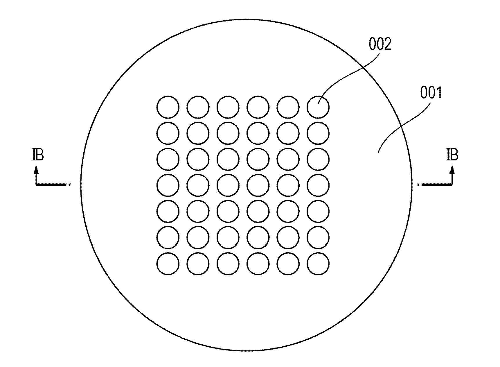
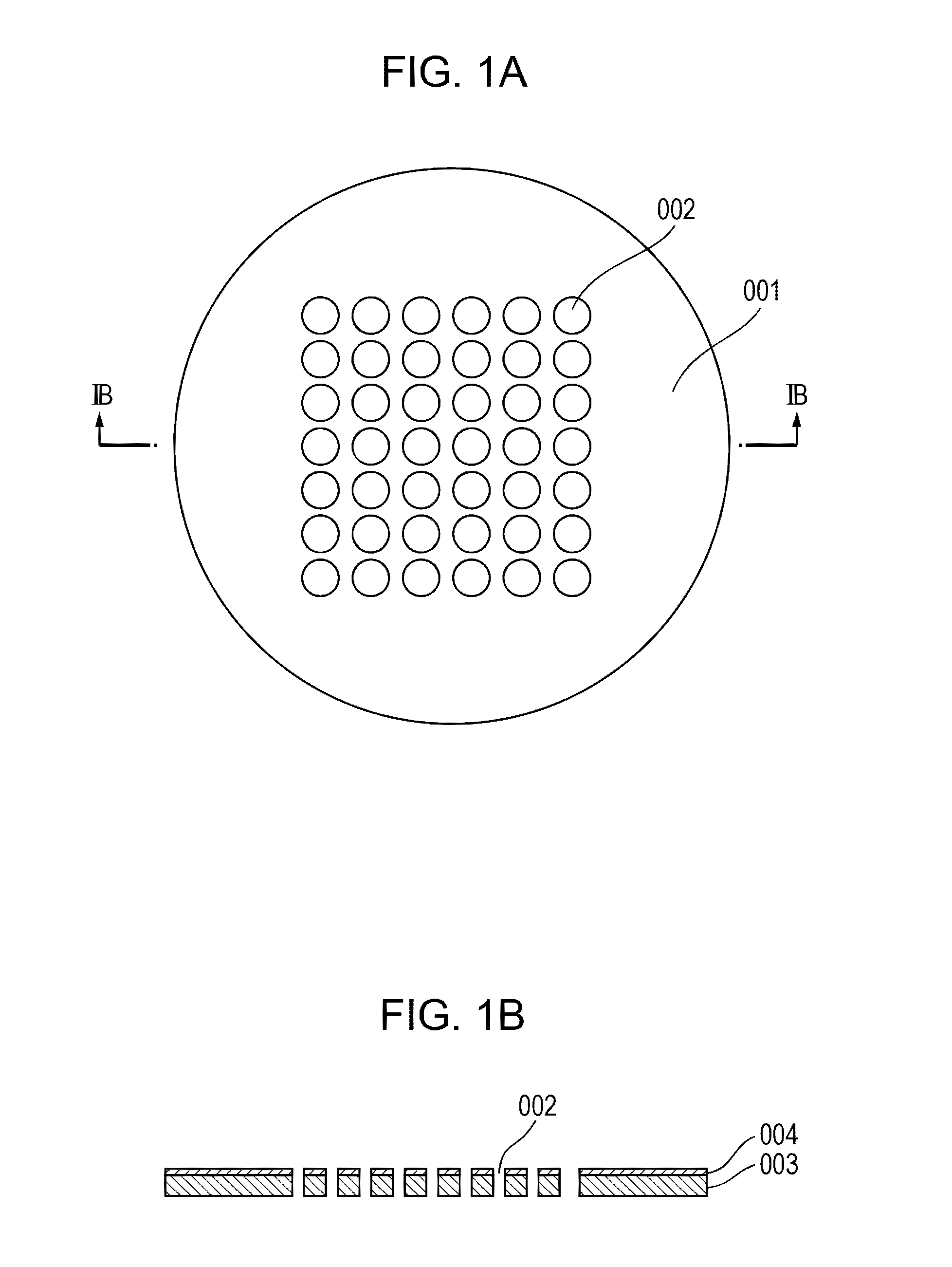
[0024]FIG. 1A is a top view of the aperture according to aspects of the present invention. A part of a charged particle beam is blocked by the aperture 001 and a part of the charged particle beam passes through through-holes 002 provided in the aperture 001 and is irradiated to an object to be exposed. Such an aperture or a combination of a plurality of the apertures is disposed on a path of the charged particle beam, so that the charged particle beam passing through the through-holes in the apertures is divided into a predetermined number of beams and / or formed into a predetermined shape.

[0025]FIG. 1B is a cross-sectional view taken along line IB-IB in FIG. 1A. A getter 004 is disposed on a surface of an aperture 003 to which the charged particle beam is irradiated. Both the aperture 003 and the getter 004 include through-holes 002 through which the charged particle beam passes.

[0026]In FIG....

second embodiment

[0036]A charged particle beam exposure apparatus, which is the present invention, will be described with reference to FIGS. 3 and 4.

[0037]FIG. 3 is a diagram showing a configuration of a multiple charged particle beam exposure apparatus using an aperture having the same configuration as that of the first embodiment of the present invention. The present embodiment is a multi-column system which includes separate projection systems.

[0038]A radiation charged particle beam drawn from a charged particle source 108 by an anode electrode 110 forms an irradiation optical system crossover 112 by a crossover adjustment optical system 111.

[0039]Here, as the charged particle source 108, a so-called thermionic type electron source such as LaB6 and BaO / W (dispenser cathode) is used.

[0040]The crossover adjustment optical system 111 includes first and second electrostatic lenses. Both the first and the second electrostatic lenses are a so-called einzel type electrostatic lens which includes three e...

third embodiment

[0057]A configuration in which a getter including a polycrystalline metal deposited film is disposed on an upper most surface of an aperture according to the present invention will be described with reference to FIG. 5.

[0058]Prior to the description of the present embodiment, a relationship between the exhaust capacity of an NEG and a crystalline structure of the NEG will be described.

[0059]An activated NEG has an active metal layer on the upper most surface of the NEG, combines with incoming gas molecules, and absorbs the gas molecules, so that the NEG exhausts the gas. Regarding the exhaust capacity of the NEG, the larger the surface area which absorbs the gas molecules, the larger the amount of gas being absorbed, so that the larger the specific surface area of the NEG, the larger the exhaust capacity of a getter formed per unit area of the aperture.

[0060]A highly crystalline metal layer having a large crystallite size, that is, a dense metal layer, has a large filling rate (dens...


PUM


Abstract

An aperture that forms a charged particle beam includes a non-evaporable getter on a surface of the aperture. The non-evaporable getter is disposed in a position to which the charged particle beam is irradiated. The degradation of the exhaust performance around a charged particle source while the charged particle source is driven is suppressed.

Description

BACKGROUND OF THE INVENTION[0001]1. Field of the Invention[0002]The present invention relates to a charged particle beam forming aperture, which constitutes an electron optical system for controlling a charged particle beam, and a charged particle beam exposure apparatus using the charged particle beam forming aperture.[0003]2. Description of the Related Art[0004]The electron beam exposure technique is a strong candidate of lithography that enables fine pattern exposure of 0.1 μm or less. A so-called multi-beam system is known, which renders a pattern on an object to be exposed by a plurality of electron beams at the same time without using a mask in order to improve throughput of electron beam exposure.[0005]In the multi-beam system, an electron beam irradiated from a high-output electron source or a high-output electron source group is introduced into an electron optical system whose openings are arranged in a one-dimensional array or a two-dimensional array, so that a plurality o...

Claims


Application Information

Patent Timeline
IPC IPC(8): G21K1/00G21K5/04
CPCG21K1/02H01J37/09H01J37/18B82Y40/00H01J7/186H01J37/3177B82Y10/00H01J7/183
Inventor YOSHITAKE, TADAYUKIANDO, YOICHI
Owner CANON KK
Why Eureka
Try Eureka