
Symmetrical partially coupled microstrip slot feed patch antenna element

a patch antenna element and microstrip technology, applied in the field of wireless communication, can solve the problems of increasing the cost of the base station antenna system in both material and labor required to construct, and reducing the cost of the dipole antenna element. , the problem and the difficulty of achieving the effect of achieving the effect of reducing the cost of the base station antenna system

Inactive Publication Date: 2013-03-14
HONG KONG APPLIED SCI & TECH RES INST
View PDF10 Cites 66 Cited by
  • Summary
  • Abstract
  • Description
  • Claims
  • Application Information

AI Technical Summary

Benefits of technology

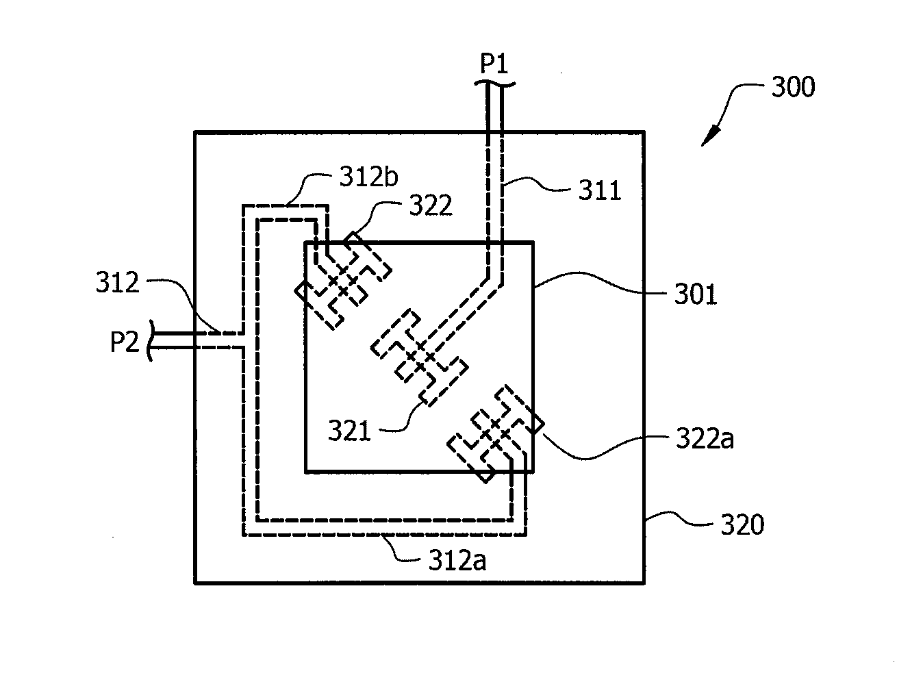
The invention describes a new antenna design that uses a microstrip slot feed to provide signals to a patch. The slots in the second signal feed are symmetrically placed near the edges of the patch, which results in isolation of -30 dB between the slots and the patch. This design also matches the radiation pattern of the slots and the patch, resulting in an improved antenna efficiency. The dual-polarized wideband patch antenna is simple to manufacture and supports a wide range of communication standards. The feed network is simplified, with no need for jumpers or cross-overs, and the signal isolation provided by the slot feed configurations results in improved antenna efficiency and supports high performance communication techniques.

Problems solved by technology

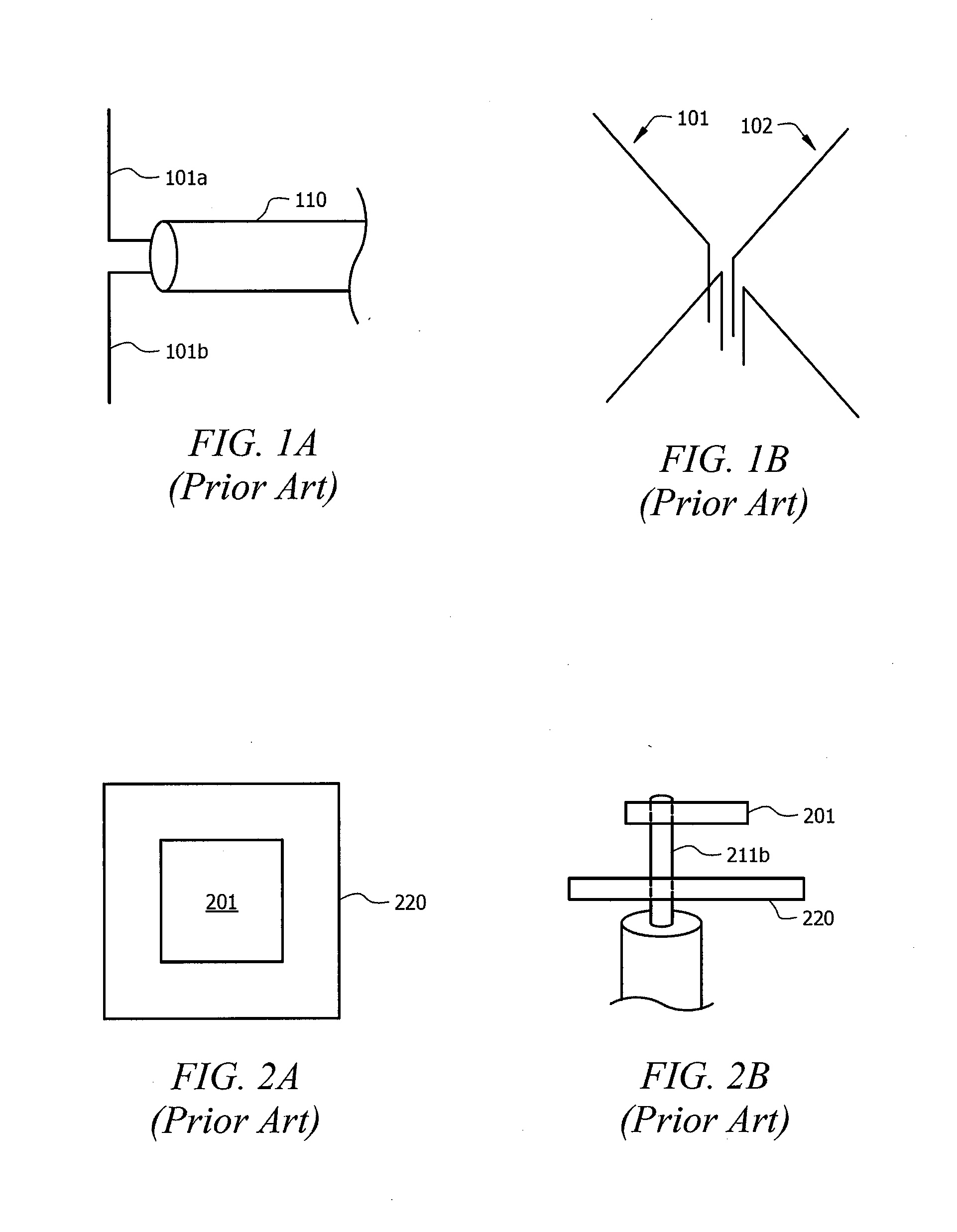
Accordingly, base station antenna systems are often costly in both material and the labor required to construct them.
Both of the foregoing configurations adds to the base station antenna system costs in both material and the labor required to construct them.
Thus, such dipole antenna elements are relatively complicated and labor intensive to manufacture.
Such a dual-polarization configuration substantially increases the complexity and cost of the antenna system.
Such a configuration is relatively expensive and / or complicated to manufacture (e.g., labor intensive to make due to soldering or similar techniques required for the electrical connection).
Moreover, the coaxial feed patch antenna element configuration has generally not been found to have good bandwidth performance characteristics.
However, the L-probe configuration continues to be relatively expensive and / or complicated to manufacture (e.g., labor intensive to position the L-probe and to provide support structure to retain the proper positioning).
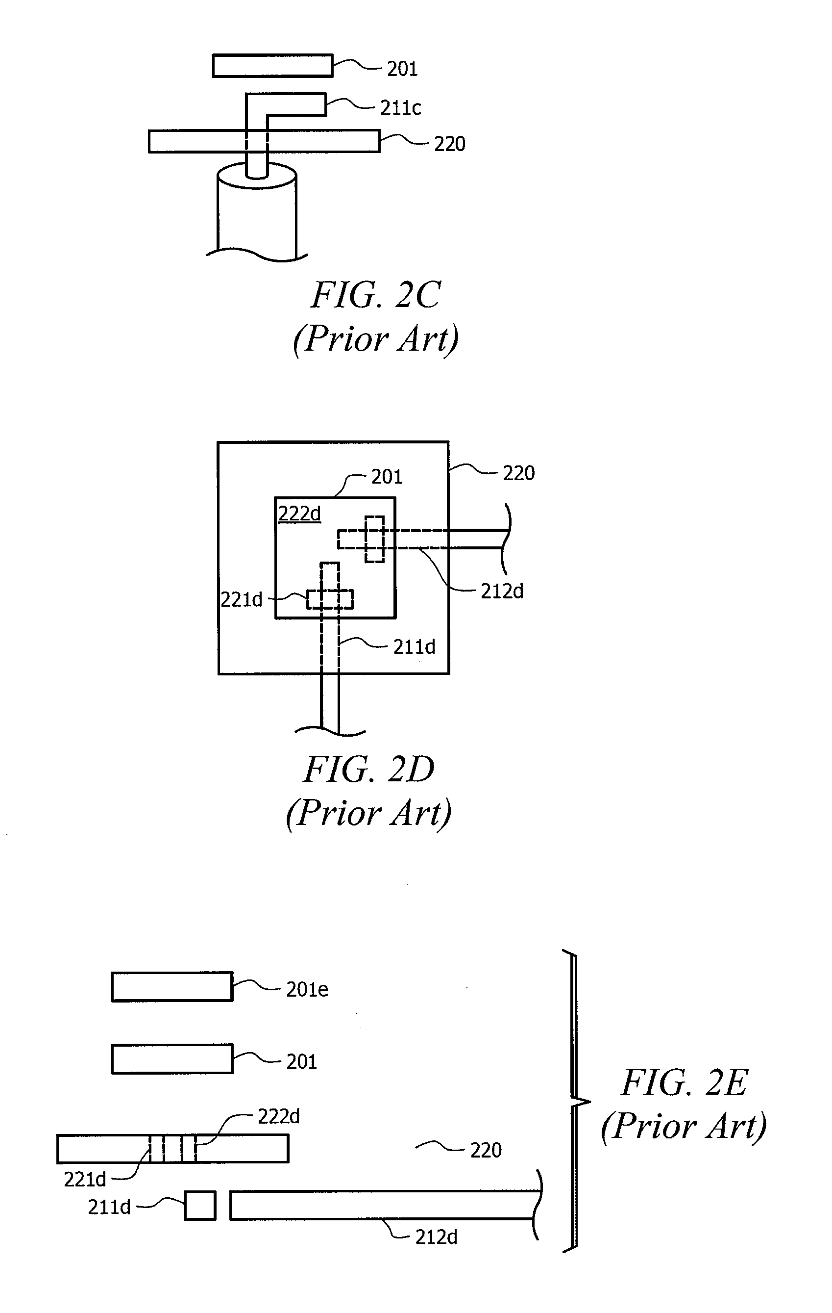
For example, microstrip slot feed configurations have been found to present difficulties with respect to impedance matching, often requiring the use of a multiple patch configuration as shown in FIG. 2E (e.g., patch 201 and patch 201e).
Although providing improved impedance matching, the use of such dual patch configurations typically results in antenna pattern distortion at various frequencies (i.e., wideband operation is affected).
Additionally, although providing for dual polarization, the asymmetry of the signal feeds results in undesired antenna pattern distortion (e.g., beams formed using an array of the microstrip slot feed antenna elements experience a shift in direction, or tilt, resulting from the asymmetric microstrip slot feed configuration).
Moreover, this printed highly decoupled input port feed configuration results in distorted antenna patterns as various frequencies.
Accordingly, the printed highly decoupled input port feed patch antenna element configuration is complicated and relatively costly to manufacture (e.g., two patches) while continuing to suffer from some of the antenna pattern distortion problems of the microstrip slot feed patch antenna element configuration.
Also, as the signal level on the slots are fully coupled to the patches, the signal level of coupling through the slots cannot be controlled and creates difficulties with respect to impedance matching.

Method used


Image

  • Symmetrical partially coupled microstrip slot feed patch antenna element
  • Symmetrical partially coupled microstrip slot feed patch antenna element
  • Symmetrical partially coupled microstrip slot feed patch antenna element

Examples


Embodiment Construction

[0027]FIGS. 3A-3E show details with respect to an embodiment of a dual-polarized wideband patch antenna configuration according to the concepts herein. The embodiment of dual-polarized wideband patch antenna element 300 illustrated in FIGS. 3A-3E is adapted to provide communication of signals associated with port 1 (P1) and port 2 (P2) using a patch antenna configuration which is relatively simple to manufacture and having excellent operating characteristics. The patch antenna element configuration and the associated signal feed configuration provides relatively wideband operation while the orthogonal configuration of the microstrip slot feeds of the two ports facilitates dual polarization operation. Moreover, the microstrip slot feed configuration of embodiments herein provides relatively high signal isolation as between the signals associated with port 1 and port 2 and the signal feed configuration is adapted to eliminate certain antenna pattern distortion issues, such as undesire...


PUM


Abstract

Systems and methods which utilize a symmetrical partially coupled microstrip slot feed patch antenna element configuration to provide highly decoupled dual-polarized wideband patch antenna elements are shown. Embodiments provide a microstrip slot feed configuration in which a slot of a first signal feed is centered with respect to the patch and further provide a microstrip slot feed configuration in which slots of a second signal feed are symmetrically disposed with respect to the center of the patch and at positions near the edges of the patch. The microstrip feed utilized in communicating signals with respect to the slots of the second signal feed is adapted to provide signals of substantially equal amplitude and 180° out of phase with respect to each other according to embodiments. The second signal feed configuration utilized according to embodiments provides partial coupling between the patch and the second signal feed.

Description

TECHNICAL FIELD[0001]The invention relates generally to wireless communications and, more particularly, to dual-polarized wideband patch antenna configurationsBACKGROUND OF THE INVENTION[0002]Various configurations of antenna elements and antenna array configurations have been used for providing wireless communications in systems such as Global System for Mobile Communications (GSM), third generation mobile telecommunications (3G), fourth generation mobile telecommunications (4G), 3GPP Long Term Evolution (LTE), Universal Mobile Telecommunications System (UMTS), wireless fidelity (Wi-Fi), Worldwide Interoperability for Microwave Access (WiMAX), and Wireless Broadband (WiBro). In providing broadband wireless communications, a base station, access point, or other communication node (collectively referred to herein as base stations) often include an array of antenna elements operable to illuminate a service area for providing broadband wireless communications.[0003]An antenna element a...

Claims


Application Information

Patent Timeline
Patent Type & Authority Applications(United States)
IPC IPC(8): H01Q1/38H01Q5/00
CPCH01Q1/246H01Q21/08H01Q9/0457
Inventor MAK, ANGUS C. K.ROWELL, CORBETT R.LAI, HAU WAH
Owner HONG KONG APPLIED SCI & TECH RES INST
Learn More