Polarizing film, display device and production process thereof

Active Publication Date: 2013-03-21
FUJIFILM CORP
View PDF5 Cites 18 Cited by
  • Summary
  • Abstract
  • Description
  • Claims
  • Application Information

AI Technical Summary

Benefits of technology

[0039]The present invention is capable of providing a high contrast polarizing film showing high dichr

Problems solved by technology

When used in a polarizing device, however, the heat resistance and the light resistance of iodine are not sufficient because of a significant sublimation property of iodine.
These organic dyes, however, have a problem that only a polarizing device having fairly poor dichroism is obtained as compared with iodine.
This method also has problems such as troublesome processes of a stretching treatment and the like.
However, these polarizing devices have a problem that the devices tends to cause a grain boundary with a domain, thereby causing scattering and depolarization since these polarizing devices have a low symmetry and high order structure.
An azo dye having a substituent imparting water-solubility such as a sulfo group, a carboxyl group and the like described in Patent Document 2 is difficult to subject to a uniform alignment treatment by heat aging like in the ca

Method used


Image

  • Polarizing film, display device and production process thereof
  • Polarizing film, display device and production process thereof
  • Polarizing film, display device and production process thereof

Examples


Example

Example 1

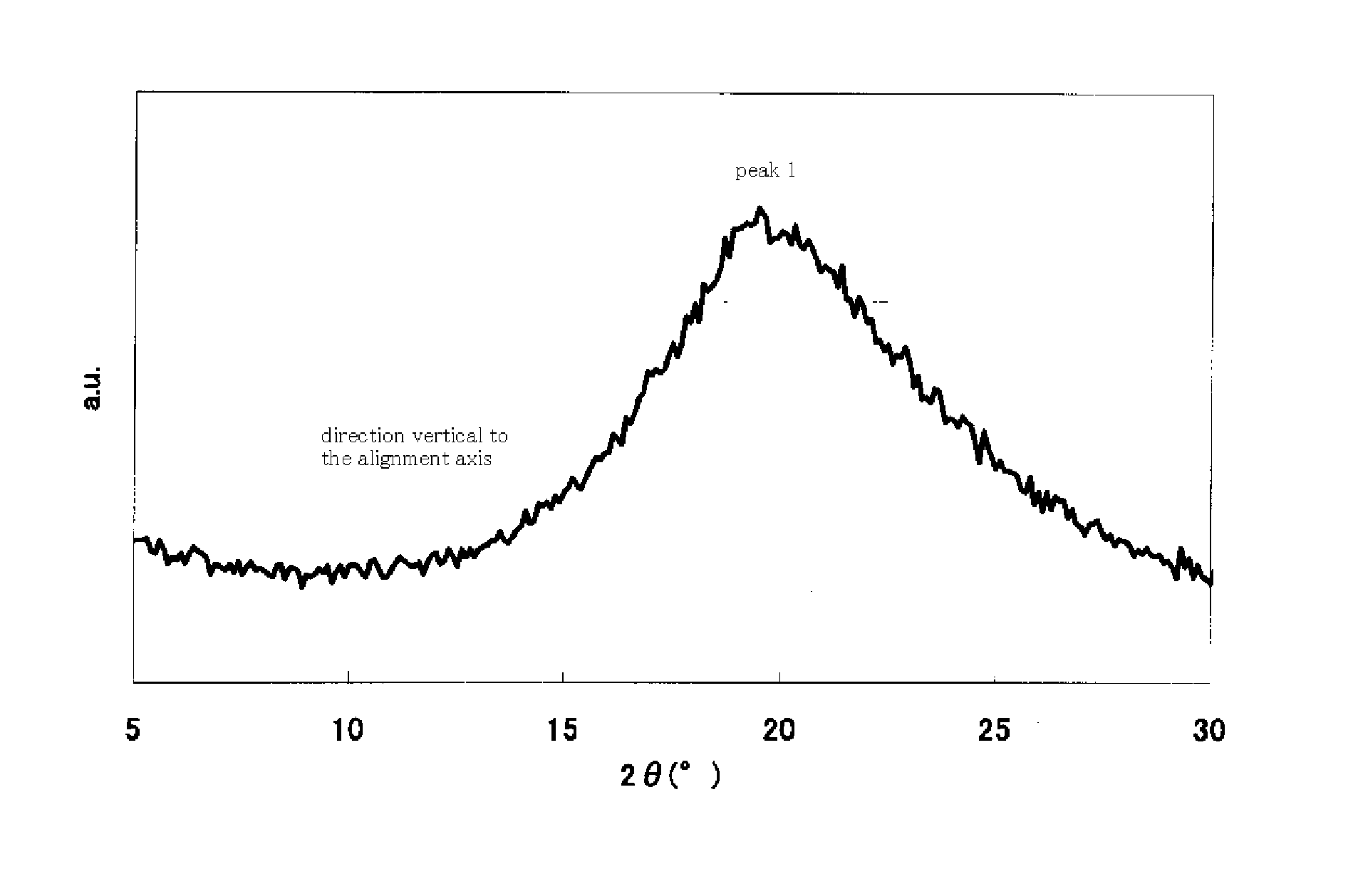
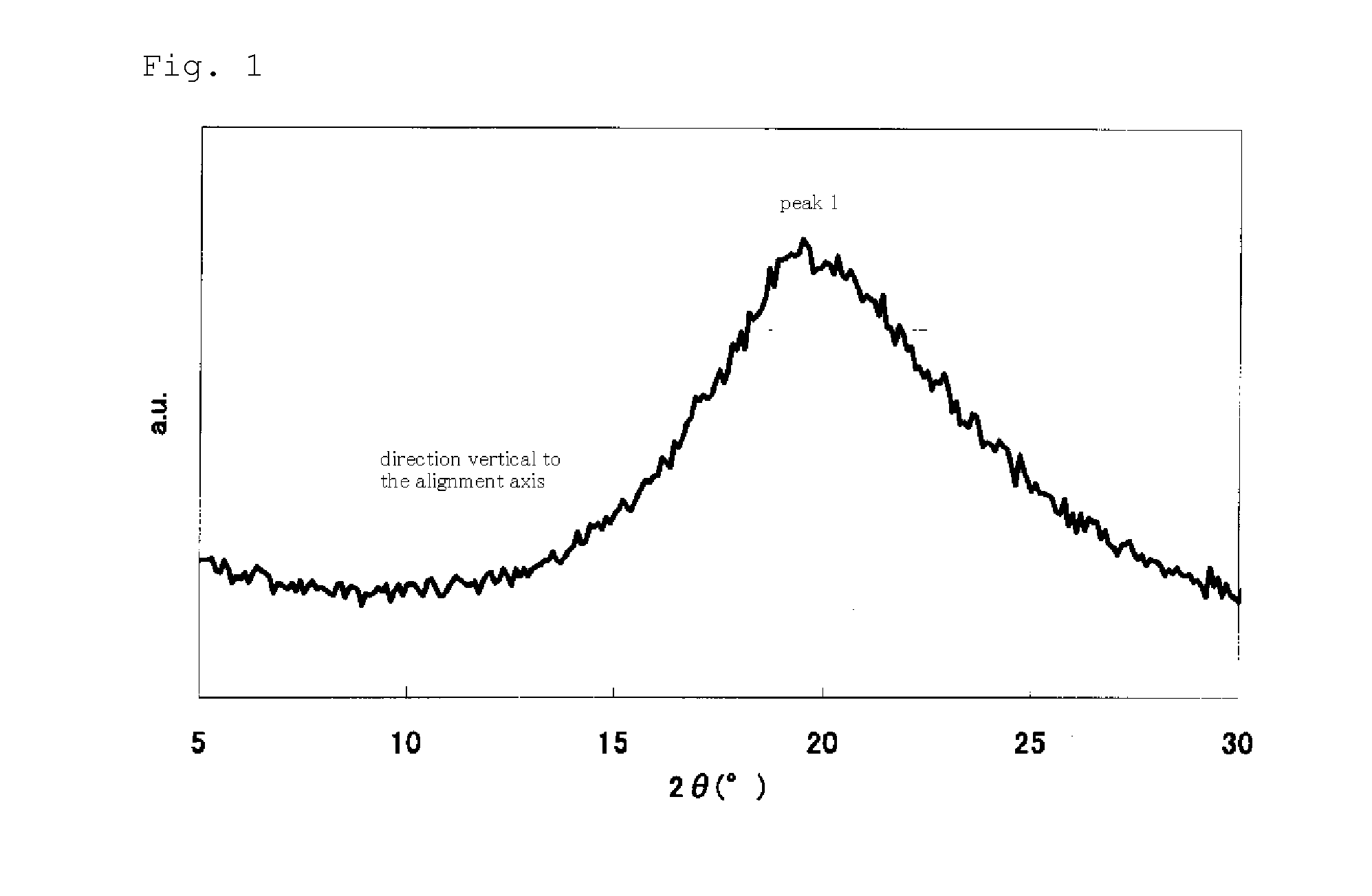
[0356]To 1 part by mass of an optical alignment material E-1 having the following structure were added 49.5 parts by mass of N-methylpyrrolidone and 49.5 parts by mass of 2-butoxyethanol, and the resultant solution was filtrated under pressure through a 0.45 μm film filter. The resultant coating solution for photo alignment film was spin-coated on a glass substrate, and dried at 100° C. for 1 minute. The resultant coated film was irradiated with a linear polarized ultraviolet ray using a polarized ultraviolet exposing apparatus (illuminance: 140 mW, irradiation time: 35 seconds, irradiance amount: 5 J / cm2).

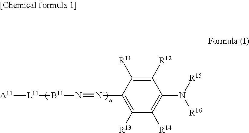
[0357]On the resultant glass substrate with the photo alignment film, a dichroic dye solution prepared by dissolving 1 part by mass of a magenta azo dye A-16 having the following structure (compound of the formula (I)) in 99 parts by mass of chloroform was spin-coated, to form a light absorption anisotropic film. As described above, a polarizing film was fabricated. The d...

Example

Example 2

[0358]To 2 parts by mass of an optical alignment material II-1 having the following structure was added 98 parts by mass 1,1,2-trichloroethane and the resultant solution was filtrated under pressure through a 0.45 μm film filter. The resultant coating solution for photo alignment film was spin-coated on a glass substrate, and dried at 100° C. for 1 minute. The resultant coated film was irradiated with a linear polarized ultraviolet ray using a polarized ultraviolet exposing apparatus (illuminance: 140 mW, irradiation time: 35 seconds, irradiance amount: 5 J / cm2), then, heated at 230° C. for 5 minutes.

[0359]On the resultant glass substrate with the photo alignment film, a dichroic dye solution prepared by dissolving 1 part by mass of a magenta azo dye C-9 having the following structure (compound of the formula (I)) in 99 parts by mass of chloroform was spin-coated, to form a light absorption anisotropic film. As described above, a polarizing film was fabricated. The dichroic...

Example

Example 3

[0360]To 1 part by mass an optical alignment material II-12 having the following structure was added 99 parts by mass of tetrahydrofuran, and the resultant solution was filtrated under pressure through a 0.45 μm film filter. The resultant coating solution for photo alignment film was spin-coated on a glass substrate, and dried at 100° C. for 1 minute. The resultant coated film was irradiated with a linear polarized ultraviolet ray using a polarized ultraviolet exposing apparatus (illuminance: 140 mW, irradiation time: 35 seconds, irradiance amount: 5 J / cm2).

[0361]On the resultant glass substrate with the photo alignment film, a dichroic dye solution prepared by dissolving 0.5 parts by mass of the above-described magenta azo dye A-16 (compound of the formula (I)) and 0.5 parts by mass of a magenta azo dye B-4 having the following structure (compound of formula (I)) in 99 parts by mass of chloroform was spin-coated, to form a light absorption anisotropic film. As described ab...


PUM


Abstract

A polarizing film comprising a substrate, and a photo alignment film and a light absorption anisotropic film laminated on the substrate in this order, wherein the light absorption anisotropic film has a content ratio of 30% by mass or less of a liquid crystalline non-colorable low molecular weight compound and is obtained by fixing the alignment of a dichroic dye composition comprising at least one nematic liquid crystalline azo dichroic dye; in X-ray diffraction measurement thereof, diffraction peaks derived from periodic structure along a vertical direction to the alignment axis are present, the period indicated by at least one of the diffraction peaks is 3.0 to 15.0A and an intensity of the diffraction peak does not show a maximum value in the range of ±70° of the film normal line direction in a plane vertical to the alignment axis.

Description

TECHNICAL FIELD [0001]The present invention relates to a polarizing film and a display device using the polarizing film, particularly to a polarizing film having reduced depolarization and a process for producing the same.BACKGROUND ART [0002]When an attenuation function, a polarization function, a scattering function, a light shielding function and the like of irradiating lights including a laser beam and natural light are required, there are conventionally used apparatuses operating according to theories varying depending on respective functions. Hence, also articles corresponding to these functions are produced by production steps varying depending on respective functions. For example, for LCD (liquid crystal device), a linear polarizing plate and a circular polarizing plate are used to control optical rotation and birefringence in display. Also in OLED (organic electroluminescence device), a circular polarizing plate is used for prevention of reflection of a light from the outsi...

Claims


Application Information

Patent Timeline
IPC IPC(8): G01N23/20
CPCC09K19/601G02F1/133528C09B29/081C09B29/083C09B31/043C09B31/18C09B31/30C09B33/22C09B56/02C09B56/06G02B5/30G02B1/10B05D3/062B05D3/0218G02F1/133788G02B5/3016
Inventor MORISHIMA, SHINICHIIWAHASHI, NOBUTAKAOGIYAMA, MASASHIUEMURA, MINORU
Owner FUJIFILM CORP
Why Eureka
Try Eureka