Microfluidic systems and methods for reducing the exchange of molecules between droplets

a microfluidic system and droplet technology, applied in fluid controllers, laboratory glassware, instruments, etc., can solve the problems of high detrimental, surface adsorption of reactants, and the limit of the smallest volume of reagents that can effectively be used, so as to prevent the coalescence of microdroplets

Active Publication Date: 2013-05-02
BIO RAD LAB INC
View PDF7 Cites 230 Cited by
  • Summary
  • Abstract
  • Description
  • Claims
  • Application Information

AI Technical Summary

Benefits of technology

[0009]The first concentration is sufficient to stabilize the microdroplets against coalescing with each other in the first carrier fluid. Preferably, the first concentration prevents coalescence of the microdroplets. The first concentration is determined, at least in part, based on stabilizing the microdroplets over a time frame determined by a reaction and/or detection of the one or more biological and/or chemical materials.
[0010]The second concentration...

Problems solved by technology

However, virtually all microfluidic devices are based on flows of streams of fluids; this sets a limit on the smallest volume of reagent that can effectively be used because of the contaminating effects of diffusion and surface adsorption.
As the dimensions of small volumes shrink, diffusion becomes the dominant mechanism for mixing, leading to dispersion of reactants; moreover, surface adsorption of reactants, while small, can be highly detrimental when the concentrations are low and volumes are small.
As a result, current microfluidic technologies cannot be reliably used for applications involving minute quantities of reagent; for example, bioassays on single cells or library searches involving single beads are not easily performed.
However, essentially all enabling technology...

Method used


Image

  • Microfluidic systems and methods for reducing the exchange of molecules between droplets
  • Microfluidic systems and methods for reducing the exchange of molecules between droplets
  • Microfluidic systems and methods for reducing the exchange of molecules between droplets

Examples


example 1

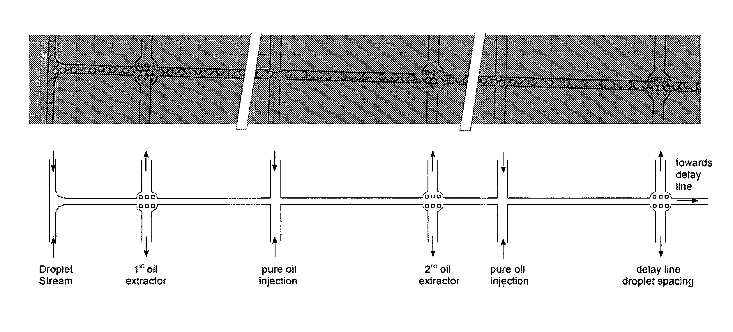
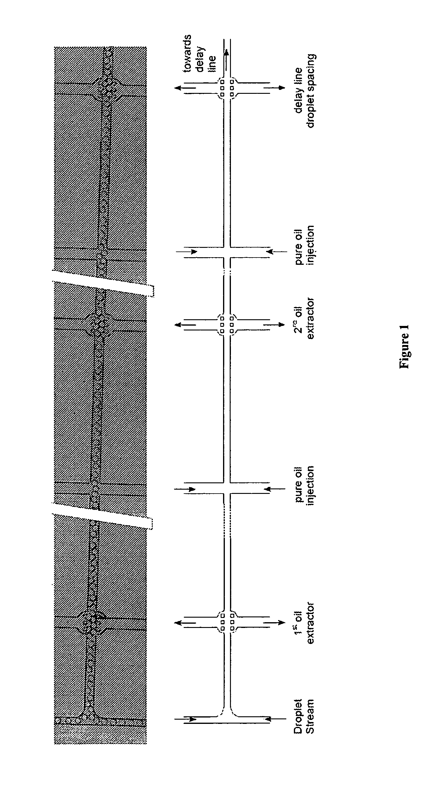
[0220]The continuous stream of droplets in surfactant loaded oil is subsequently subjected to several actively controlled extractions of the continuous fluorinated oil phase and injections of pure oil (See, FIG. 1). This apparatus and method first reduces the volume fraction of surfactant loaded oil, thus densifying the droplets in the main channel after the extraction. Subsequent injection of pure oil dilutes the surfactant in the continuous phase. This injection of pure oil also serves to respace the droplets. This can be repeated several times, which reduces the micellar concentration considerably. Additional oil extractions can be added to control the droplet density in the delay line. (See, the right margin of FIG. 1).

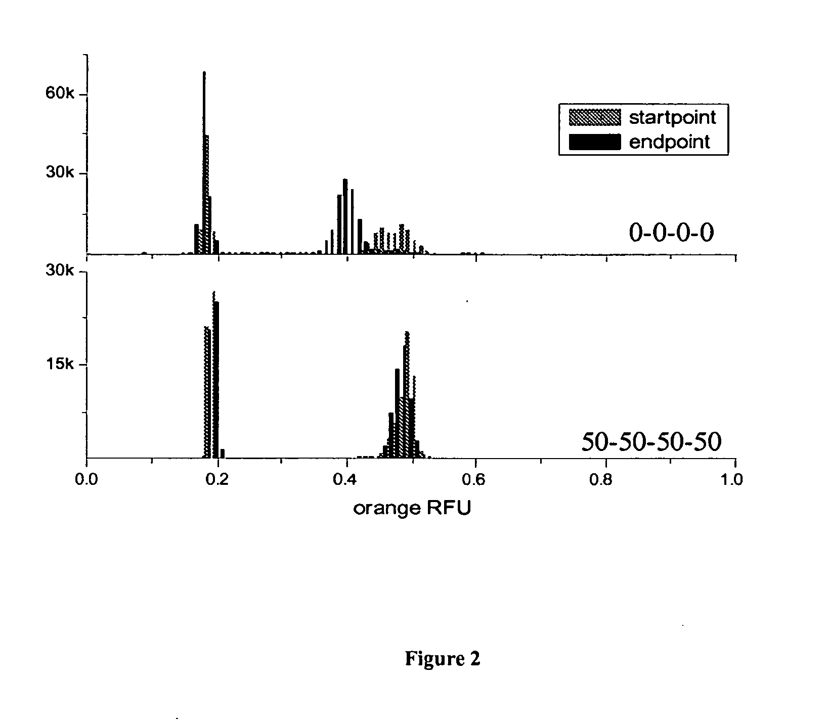
[0221]The effect of such an actively controlled oil exchange on the exchange of small fluorescent molecules between droplets was monitored in a delay line on chip (See, FIG. 2). The fluorophore under investigation was resorufin. Two droplet populations with differ...

example 2

[0223]In this example, droplets are produced and then transferred from the surfactant loaded oil stream into a surfactant free oil stream making use of the laminar flow conditions in a microfluidic device. The focus is to switch the droplets in an exchange chamber from one laminar oil stream to an adjacent laminar stream. In this way, the aqueous droplets leave the surfactant loaded oil stream after a period of time sufficiently long to stabilize the interface and enter a surfactant free oil stream. The droplets are now in a completely micelle free environment and even if surfactant detaches from the interface and enters the continuous phase, this process is slow and will end when the CMC is reached. A schematic design of the exchange chamber is illustrated in FIG. 3. The droplets enter the chamber from the lower left and their stream (surfactant loaded oil and aqueous droplets) is paralleled by a stream of pure oil, entering from the lower right. Due to the laminar flow regime the ...

example 3

[0230]In this example, droplets are created and directed into a reservoir (e.g., vial or other container) that is mounted on top of the microfluidic device (See, FIG. 8). This reservoir is filled with pure oil and thus the aqueous droplets will cream / rise towards the top of the reservoir due to the high buoyancy force of water in fluorinated oil (the density difference is about 1.7). Additionally, pure oil is injected from the top of the reservoir which creates a stream of pure oil in the inverse direction of the creaming droplets. The outlet of the reservoir, necessary to avoid an over pressure, is also at the bottom. The principle of this device is to transfer the droplets to a surfactant free environment and to continuously wash them in this environment. The emulsion can be stored in this reservoir for long periods of time (longer than in on-chip delay lines) and be reinjected. The reinjection is achieved by inverting the flow directions: pure oil is pushed from both bottom inlet...


PUM


Abstract

The present invention generally relates to systems and methods to create stable emulsions with low rates of exchange of molecules between microdroplets.

Description

CROSS-REFERENCE TO RELATED APPLICATIONS[0001]This application claims priority to, and the benefit of, U.S. Patent Application No. 61 / 289,654 filed Dec. 23, 2009, the contents of which are incorporated herein by reference in its entirety.FIELD OF INVENTION[0002]The present invention is directed to systems and methods to create stable emulsions with low rates of exchange of molecules between droplets.BACKGROUND OF THE INVENTION[0003]The manipulation of fluids to form fluid streams of desired configuration, discontinuous fluid streams, droplets, particles, dispersions, etc., for purposes of fluid delivery, product manufacture, analysis, and the like, is a relatively well-studied art. Microfluidic systems have been described in a variety of contexts, typically in the context of miniaturized laboratory (e.g., clinical) analysis. Other uses have been described as well. For example, WO 01 / 89788; WO 2006 / 040551; U.S. Patent Application Publication No. 2009 / 0005254; WO 2006 / 040554; U.S. Pate...

Claims


Application Information

Patent Timeline
IPC IPC(8): G01N1/38
CPCG01N1/38B01L3/502761B01L3/502784B01L7/52B01L2200/0652B01L2200/0673B01L2300/0816B01L2300/0864B01L2300/0867B01L2400/0424B01L2400/0469B01L2400/086G01N33/5302C12M25/01G01N15/1459G01N2015/1006G01N2015/149
Inventor KLEINSCHMIDT, FELIXGRIFFITHS, ANDREW DAVIDCARON, FRANÇOISEL HARRAK, ABDESLAMBROUZES, ERICLINK, DARREN
Owner BIO RAD LAB INC
Why Eureka
Try Eureka